Cirkit Designer Logo
Cirkit Designer
Your all-in-one circuit design IDE
Home / 
Component Documentation

How to Use NRF24L01 Adapter: Examples, Pinouts, and Specs

Image of NRF24L01 Adapter
Cirkit Designer LogoDesign with NRF24L01 Adapter in Cirkit Designer

Introduction

The NRF24L01 Adapter is a wireless communication module that facilitates the use of the NRF24L01 transceiver chip. This adapter is designed to simplify the connection between the NRF24L01 module and microcontrollers, such as the Arduino UNO, by providing the necessary voltage regulation and signal level conversion. It is widely used in applications requiring wireless data transmission, such as remote control systems, telemetry, home automation, and sensor networks.

Explore Projects Built with NRF24L01 Adapter

Use Cirkit Designer to design, explore, and prototype these projects online. Some projects support real-time simulation. Click "Open Project" to start designing instantly!
Arduino Nano Wireless Communication System with nRF24L01 Module
Image of drone reciever: A project utilizing NRF24L01 Adapter in a practical application
This circuit connects an nRF24L01 wireless transceiver module to an Arduino Nano microcontroller through an adapter board. The Arduino Nano is configured to communicate with the nRF24L01 via SPI (Serial Peripheral Interface), using pins D9 and D10 for chip enable (CE) and chip select (CSN), and pins D11 to D13 for the SPI bus (MOSI, MISO, SCK). An electrolytic capacitor is connected across the power supply lines likely for power stabilization.
Cirkit Designer LogoOpen Project in Cirkit Designer
Arduino Nano and NRF24L01 Wireless Communication Module
Image of Reciever: A project utilizing NRF24L01 Adapter in a practical application
This circuit features an Arduino Nano microcontroller interfaced with an NRF24L01 wireless transceiver module via an adapter. The setup is designed for wireless communication, with the Arduino controlling the transceiver through SPI and digital I/O pins, and the code provided is a basic template for further development.
Cirkit Designer LogoOpen Project in Cirkit Designer
Arduino UNO with NRF24L01 Wireless Communication and Analog Input Control
Image of loco receiver 1: A project utilizing NRF24L01 Adapter in a practical application
This circuit features an Arduino UNO connected to an NRF24L01 Adapter for wireless communication, powered by a 12V supply. It includes two potentiometers for analog input and three pushbuttons for digital input, with the Arduino managing these interfaces and potentially processing and transmitting data wirelessly.
Cirkit Designer LogoOpen Project in Cirkit Designer
Arduino Nano Controlled NRF24L01 Wireless Communication System
Image of transmitter: A project utilizing NRF24L01 Adapter in a practical application
This circuit features an Arduino Nano microcontroller interfaced with an NRF24L01 Adapter for wireless communication. A toggle switch is used to send a signal to the NRF24L01 when activated, which is indicated by an LED connected through a resistor. The Arduino Nano is programmed to send a message via the NRF24L01 when the switch is pressed, and the LED reflects the switch's state.
Cirkit Designer LogoOpen Project in Cirkit Designer

Explore Projects Built with NRF24L01 Adapter

Use Cirkit Designer to design, explore, and prototype these projects online. Some projects support real-time simulation. Click "Open Project" to start designing instantly!
Image of drone reciever: A project utilizing NRF24L01 Adapter in a practical application
Arduino Nano Wireless Communication System with nRF24L01 Module
This circuit connects an nRF24L01 wireless transceiver module to an Arduino Nano microcontroller through an adapter board. The Arduino Nano is configured to communicate with the nRF24L01 via SPI (Serial Peripheral Interface), using pins D9 and D10 for chip enable (CE) and chip select (CSN), and pins D11 to D13 for the SPI bus (MOSI, MISO, SCK). An electrolytic capacitor is connected across the power supply lines likely for power stabilization.
Cirkit Designer LogoOpen Project in Cirkit Designer
Image of Reciever: A project utilizing NRF24L01 Adapter in a practical application
Arduino Nano and NRF24L01 Wireless Communication Module
This circuit features an Arduino Nano microcontroller interfaced with an NRF24L01 wireless transceiver module via an adapter. The setup is designed for wireless communication, with the Arduino controlling the transceiver through SPI and digital I/O pins, and the code provided is a basic template for further development.
Cirkit Designer LogoOpen Project in Cirkit Designer
Image of loco receiver 1: A project utilizing NRF24L01 Adapter in a practical application
Arduino UNO with NRF24L01 Wireless Communication and Analog Input Control
This circuit features an Arduino UNO connected to an NRF24L01 Adapter for wireless communication, powered by a 12V supply. It includes two potentiometers for analog input and three pushbuttons for digital input, with the Arduino managing these interfaces and potentially processing and transmitting data wirelessly.
Cirkit Designer LogoOpen Project in Cirkit Designer
Image of transmitter: A project utilizing NRF24L01 Adapter in a practical application
Arduino Nano Controlled NRF24L01 Wireless Communication System
This circuit features an Arduino Nano microcontroller interfaced with an NRF24L01 Adapter for wireless communication. A toggle switch is used to send a signal to the NRF24L01 when activated, which is indicated by an LED connected through a resistor. The Arduino Nano is programmed to send a message via the NRF24L01 when the switch is pressed, and the LED reflects the switch's state.
Cirkit Designer LogoOpen Project in Cirkit Designer

Technical Specifications

Key Technical Details

  • Operating Voltage: 3.3V (regulated by the onboard voltage regulator)
  • Communication Interface: SPI (Serial Peripheral Interface)
  • Maximum Air Data Rate: 2 Mbps
  • Frequency Range: 2.4 GHz ISM band
  • Modulation: GFSK (Gaussian Frequency Shift Keying)
  • Output Power: Adjustable from -18 dBm to +8 dBm
  • Sensitivity: Up to -82 dBm at 2 Mbps
  • Operating Temperature Range: -40°C to 85°C

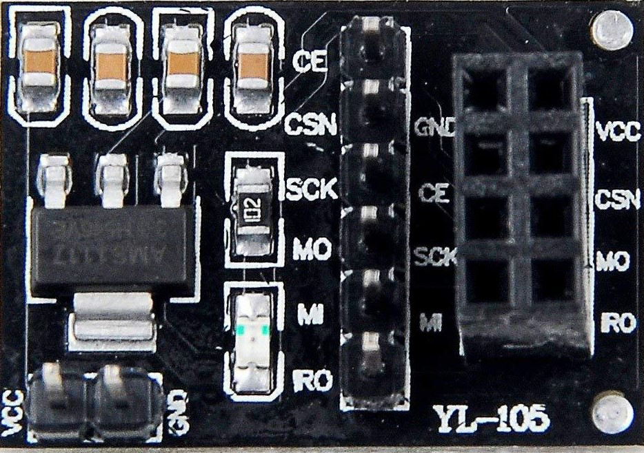
Pin Configuration and Descriptions

Pin Number Pin Name Description
1 GND Ground connection
2 VCC Power supply (3.3V input)
3 CE Chip Enable activates RX or TX mode
4 CSN SPI Chip Select (active low)
5 SCK SPI Clock
6 MOSI SPI Master Out Slave In
7 MISO SPI Master In Slave Out
8 IRQ Interrupt Request (active low)

Usage Instructions

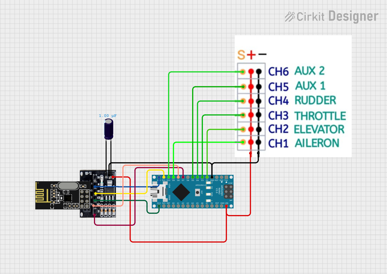
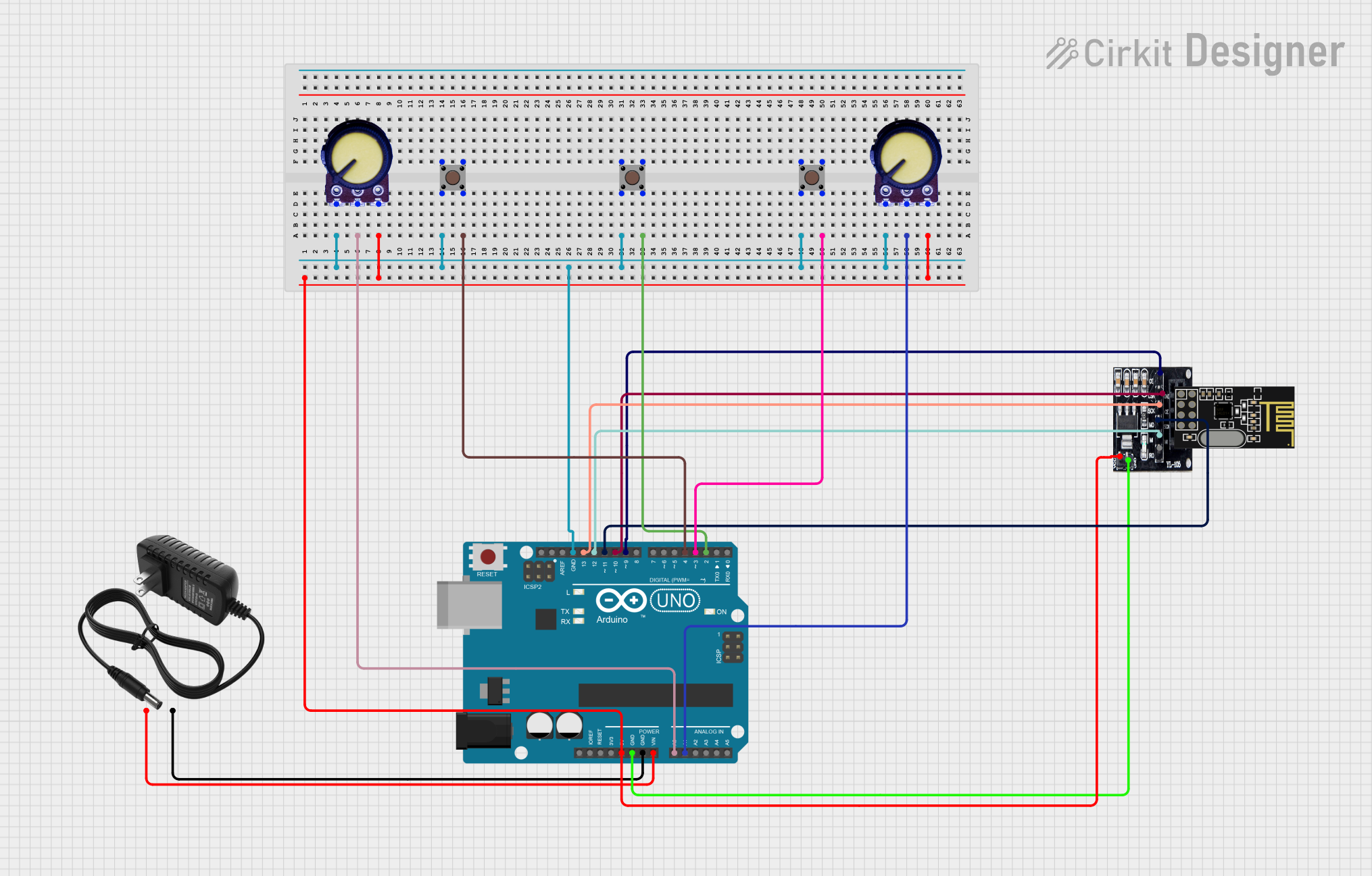
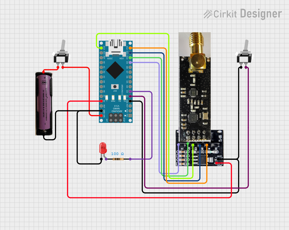
Interfacing with an Arduino UNO

  1. Power Connections:

    • Connect the VCC pin of the NRF24L01 Adapter to the 3.3V output on the Arduino UNO.
    • Connect the GND pin to one of the GND pins on the Arduino UNO.
  2. SPI Connections:

    • Connect the SCK pin to the SCK pin (Digital 13) on the Arduino UNO.
    • Connect the MOSI pin to the MOSI pin (Digital 11) on the Arduino UNO.
    • Connect the MISO pin to the MISO pin (Digital 12) on the Arduino UNO.
    • Connect the CSN pin to a digital pin on the Arduino UNO (e.g., Digital 10).
    • Connect the CE pin to a digital pin on the Arduino UNO (e.g., Digital 9).
  3. Software Setup:

    • Install the RF24 library in the Arduino IDE to interface with the NRF24L01 module.
    • Use the library functions to initialize the module, set the frequency channel, configure the data rate, and set the transmission power.
  4. Example Code:

    #include <SPI.h>
    #include <nRF24L01.h>
    #include <RF24.h>
    
    // Set up nRF24L01 radio on SPI bus plus pins 9 & 10
    RF24 radio(9, 10);
    
    void setup() {
      // Initialize the NRF24L01 on the SPI bus
      if (!radio.begin()) {
        Serial.println(F("radio hardware is not responding!!"));
        while (1) {} // hold in infinite loop
      }
      // Set the PA Level low to prevent power supply related issues
      radio.setPALevel(RF24_PA_LOW);
      // Set the channel to use
      radio.setChannel(76);
      // Set data rate to 1Mbps (RF24_250KBPS, RF24_1MBPS, RF24_2MBPS)
      radio.setDataRate(RF24_1MBPS);
    }
    
    void loop() {
      // User code to send and receive data
    }
    
    • Ensure that the radio.begin() function is called in the setup() to initialize the radio.
    • Adjust the setPALevel, setChannel, and setDataRate functions according to your application needs.

Important Considerations and Best Practices

  • Always use a 3.3V power supply for the VCC pin to avoid damaging the NRF24L01 chip.
  • Keep the antenna area of the NRF24L01 module clear of metal objects to ensure proper signal transmission.
  • Use capacitors (e.g., 10uF electrolytic and a 0.1uF ceramic) across the power supply pins to filter out noise.
  • For longer distances, consider using the NRF24L01+PA+LNA version with an external antenna.

Troubleshooting and FAQs

Common Issues

  • No Communication: Ensure that the SPI connections are correct and that the selected pins for CE and CSN are configured properly in the code.
  • Low Range: Check the antenna and ensure there are no obstructions or interference from other wireless devices.
  • Power Issues: Use capacitors to stabilize the power supply to the NRF24L01 module.

Solutions and Tips

  • Data Transmission Errors: Lower the data rate or increase the PA level to improve signal strength and reliability.
  • Interference: Change the communication channel to avoid interference from other 2.4 GHz devices like Wi-Fi routers.

FAQs

Q: Can I use the NRF24L01 Adapter with a 5V Arduino? A: Yes, but ensure that the VCC pin is connected to a 3.3V output, and the logic level is compatible or use a level shifter.

Q: How many NRF24L01 modules can communicate with each other? A: The NRF24L01 can configure up to 6 receiver addresses, allowing one transmitter to communicate with up to 6 receivers in a star network topology.

Q: What is the maximum range of the NRF24L01 module? A: The range depends on many factors, including the PA level, data rate, and environmental conditions. With the basic module and optimal conditions, the range can be up to 100 meters. With the PA+LNA version and an external antenna, it can be significantly more.

For further assistance, consult the NRF24L01 datasheet and the RF24 library documentation.