Cirkit Designer Logo
Cirkit Designer
Your all-in-one circuit design IDE
Home / 
Component Documentation

How to Use Adafruit Bi-Color 24-Bar Bargraph w I2C Backpack: Examples, Pinouts, and Specs

Image of Adafruit Bi-Color 24-Bar Bargraph w I2C Backpack
Cirkit Designer LogoDesign with Adafruit Bi-Color 24-Bar Bargraph w I2C Backpack in Cirkit Designer

Introduction

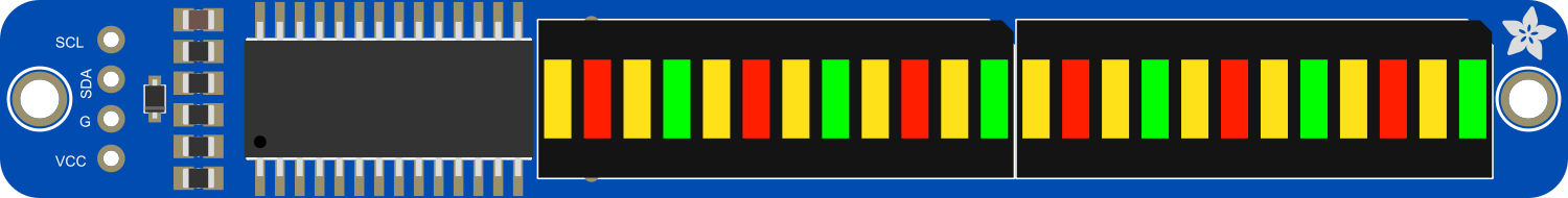
The Adafruit Bi-Color 24-Bar Bargraph with I2C Backpack is a versatile and visually appealing LED display module. It features 24 individual segments, each capable of displaying red or green light, or a combination of both to create a yellow color. This component is ideal for creating visual indicators and bar graphs for a variety of applications, including audio level meters, battery monitors, and other multi-channel monitoring systems.

Explore Projects Built with Adafruit Bi-Color 24-Bar Bargraph w I2C Backpack

Use Cirkit Designer to design, explore, and prototype these projects online. Some projects support real-time simulation. Click "Open Project" to start designing instantly!
ESP32-Based Weather Station with BME280 and DS18B20 Sensors, Battery-Powered and Wi-Fi Enabled
Image of Copy of Circuit Diagram Proto: A project utilizing Adafruit Bi-Color 24-Bar Bargraph w I2C Backpack in a practical application
This circuit is a weather monitoring system that uses an ESP32 microcontroller to read temperature data from a DS18B20 sensor and pressure data from a BME280 sensor. The data is displayed on a 20x4 I2C LCD panel, and the system can communicate via a SIM800L module. A piezo buzzer is included for audible alerts, and the entire system is powered by a 5V battery.
Cirkit Designer LogoOpen Project in Cirkit Designer
Raspberry Pi 4B with I2C Current Sensing and OLED Display
Image of iot task 2: A project utilizing Adafruit Bi-Color 24-Bar Bargraph w I2C Backpack in a practical application
This circuit features a Raspberry Pi 4B as the central processing unit, interfaced with an Adafruit ADS1115 16-bit I2C ADC for analog-to-digital conversion and a 0.96" OLED display for visual output. The ADC is connected to a current sensor for measuring electrical current, with the sensor's output connected to the ADC's AIN0 pin and the burden resistor connected to AIN1. The Raspberry Pi communicates with both the ADC and the OLED display over the I2C bus, using GPIO2 (SDA) and GPIO3 (SCL) for data exchange.
Cirkit Designer LogoOpen Project in Cirkit Designer
Battery-Powered Sensor Hub with Adafruit QT Py RP2040 and OLED Display
Image of 512: A project utilizing Adafruit Bi-Color 24-Bar Bargraph w I2C Backpack in a practical application
This circuit features an Adafruit QT Py RP2040 microcontroller interfacing with an MPU-6050 accelerometer, an Adafruit APDS-9960 sensor, and a 0.96" OLED display via I2C communication. It is powered by a 3.7V LiPo battery and includes a green LED with a current-limiting resistor connected to an analog pin of the microcontroller.
Cirkit Designer LogoOpen Project in Cirkit Designer
Battery-Powered Smart Light with Proximity Sensor and OLED Display using Adafruit QT Py RP2040
Image of lab: A project utilizing Adafruit Bi-Color 24-Bar Bargraph w I2C Backpack in a practical application
This circuit is a portable, battery-powered system featuring an Adafruit QT Py RP2040 microcontroller that interfaces with an OLED display, a proximity sensor, an accelerometer, and an RGB LED strip. The system is powered by a lithium-ion battery with a step-up boost converter to provide 5V for the LED strip, and it includes a toggle switch for power control. The microcontroller communicates with the sensors and display via I2C.
Cirkit Designer LogoOpen Project in Cirkit Designer

Explore Projects Built with Adafruit Bi-Color 24-Bar Bargraph w I2C Backpack

Use Cirkit Designer to design, explore, and prototype these projects online. Some projects support real-time simulation. Click "Open Project" to start designing instantly!
Image of Copy of Circuit Diagram Proto: A project utilizing Adafruit Bi-Color 24-Bar Bargraph w I2C Backpack in a practical application
ESP32-Based Weather Station with BME280 and DS18B20 Sensors, Battery-Powered and Wi-Fi Enabled
This circuit is a weather monitoring system that uses an ESP32 microcontroller to read temperature data from a DS18B20 sensor and pressure data from a BME280 sensor. The data is displayed on a 20x4 I2C LCD panel, and the system can communicate via a SIM800L module. A piezo buzzer is included for audible alerts, and the entire system is powered by a 5V battery.
Cirkit Designer LogoOpen Project in Cirkit Designer
Image of iot task 2: A project utilizing Adafruit Bi-Color 24-Bar Bargraph w I2C Backpack in a practical application
Raspberry Pi 4B with I2C Current Sensing and OLED Display
This circuit features a Raspberry Pi 4B as the central processing unit, interfaced with an Adafruit ADS1115 16-bit I2C ADC for analog-to-digital conversion and a 0.96" OLED display for visual output. The ADC is connected to a current sensor for measuring electrical current, with the sensor's output connected to the ADC's AIN0 pin and the burden resistor connected to AIN1. The Raspberry Pi communicates with both the ADC and the OLED display over the I2C bus, using GPIO2 (SDA) and GPIO3 (SCL) for data exchange.
Cirkit Designer LogoOpen Project in Cirkit Designer
Image of 512: A project utilizing Adafruit Bi-Color 24-Bar Bargraph w I2C Backpack in a practical application
Battery-Powered Sensor Hub with Adafruit QT Py RP2040 and OLED Display
This circuit features an Adafruit QT Py RP2040 microcontroller interfacing with an MPU-6050 accelerometer, an Adafruit APDS-9960 sensor, and a 0.96" OLED display via I2C communication. It is powered by a 3.7V LiPo battery and includes a green LED with a current-limiting resistor connected to an analog pin of the microcontroller.
Cirkit Designer LogoOpen Project in Cirkit Designer
Image of lab: A project utilizing Adafruit Bi-Color 24-Bar Bargraph w I2C Backpack in a practical application
Battery-Powered Smart Light with Proximity Sensor and OLED Display using Adafruit QT Py RP2040
This circuit is a portable, battery-powered system featuring an Adafruit QT Py RP2040 microcontroller that interfaces with an OLED display, a proximity sensor, an accelerometer, and an RGB LED strip. The system is powered by a lithium-ion battery with a step-up boost converter to provide 5V for the LED strip, and it includes a toggle switch for power control. The microcontroller communicates with the sensors and display via I2C.
Cirkit Designer LogoOpen Project in Cirkit Designer

Common Applications and Use Cases

  • Audio equipment: VU meters, level indicators
  • Battery charging stations: Charge level display
  • Environmental monitoring: Temperature, humidity, or air quality indicators
  • General status indicators: Network signal strength, system health monitors

Technical Specifications

Key Technical Details

  • Operating Voltage: 4.5V to 5.5V
  • Max Current per LED: 30mA
  • Communication: I2C interface
  • I2C Addresses: 0x70 (default) - 0x77 (selectable with solder jumpers)
  • Dimensions: 25mm x 125mm x 2mm / 1" x 5" x 0.08"

Pin Configuration and Descriptions

Pin Description
VCC Power supply (4.5V to 5.5V)
GND Ground connection
SDA I2C data line
SCL I2C clock line
A0 Address select bit 0 (solder jumper)
A1 Address select bit 1 (solder jumper)
A2 Address select bit 2 (solder jumper)

Usage Instructions

How to Use the Component in a Circuit

  1. Connect the VCC pin to a 5V power supply.
  2. Connect the GND pin to the ground of the power supply.
  3. Connect the SDA and SCL pins to the corresponding I2C data and clock lines on your microcontroller (e.g., Arduino UNO).
  4. If using multiple bargraphs, set unique I2C addresses by soldering the A0, A1, and A2 jumpers.

Important Considerations and Best Practices

  • Ensure that the power supply does not exceed 5.5V to prevent damage to the LEDs.
  • Limit the current to 30mA per LED to avoid overheating and ensure longevity.
  • Use pull-up resistors on the SDA and SCL lines if your microcontroller does not have built-in pull-ups.
  • When daisy-chaining multiple bargraphs, verify that the total current does not exceed the power supply's capabilities.

Example Code for Arduino UNO

#include <Wire.h>
#include <Adafruit_LEDBackpack.h>
#include <Adafruit_GFX.h>

Adafruit_BicolorMatrix matrix = Adafruit_BicolorMatrix();

void setup() {
  matrix.begin(0x70); // Initialize the bargraph display with its I2C address
}

void loop() {
  // Display a simple level meter that increases and decreases
  for (uint8_t i = 0; i < 24; i++) {
    matrix.setBar(i, LED_GREEN); // Set the bar to green
    matrix.writeDisplay();       // Update the display
    delay(100);
  }
  for (int8_t i = 23; i >= 0; i--) {
    matrix.setBar(i, LED_RED); // Set the bar to red
    matrix.writeDisplay();      // Update the display
    delay(100);
  }
}

Troubleshooting and FAQs

Common Issues

  • LEDs not lighting up: Check the power supply connections and ensure that the I2C address is correctly set.
  • Dim or flickering LEDs: Verify that the power supply is stable and can provide sufficient current.
  • Incorrect LED colors: Ensure that the setBar function is called with the correct color constants.

Solutions and Tips for Troubleshooting

  • Double-check wiring, especially the I2C connections.
  • Use a multimeter to verify the voltage at the VCC pin.
  • Check for solder bridges on the address select jumpers if the I2C address was changed.
  • Ensure that the Arduino library for the LED Backpack is correctly installed and up to date.

FAQs

Q: Can I chain multiple bargraphs together? A: Yes, you can daisy-chain multiple bargraphs by connecting the SDA and SCL lines in parallel and setting unique I2C addresses for each bargraph.

Q: What is the maximum number of bargraphs I can control with one I2C bus? A: You can control up to 8 bargraphs on a single I2C bus by using different addresses ranging from 0x70 to 0x77.

Q: Can I display colors other than red, green, and yellow? A: The bargraph is limited to red and green LEDs, which can be combined to create yellow. Other colors are not possible with this hardware.

Q: How do I install the Adafruit LED Backpack library? A: You can install the library through the Arduino Library Manager by searching for "Adafruit LED Backpack" and installing the latest version.