How to Use ESP32-38 PINS: Examples, Pinouts, and Specs
Introduction
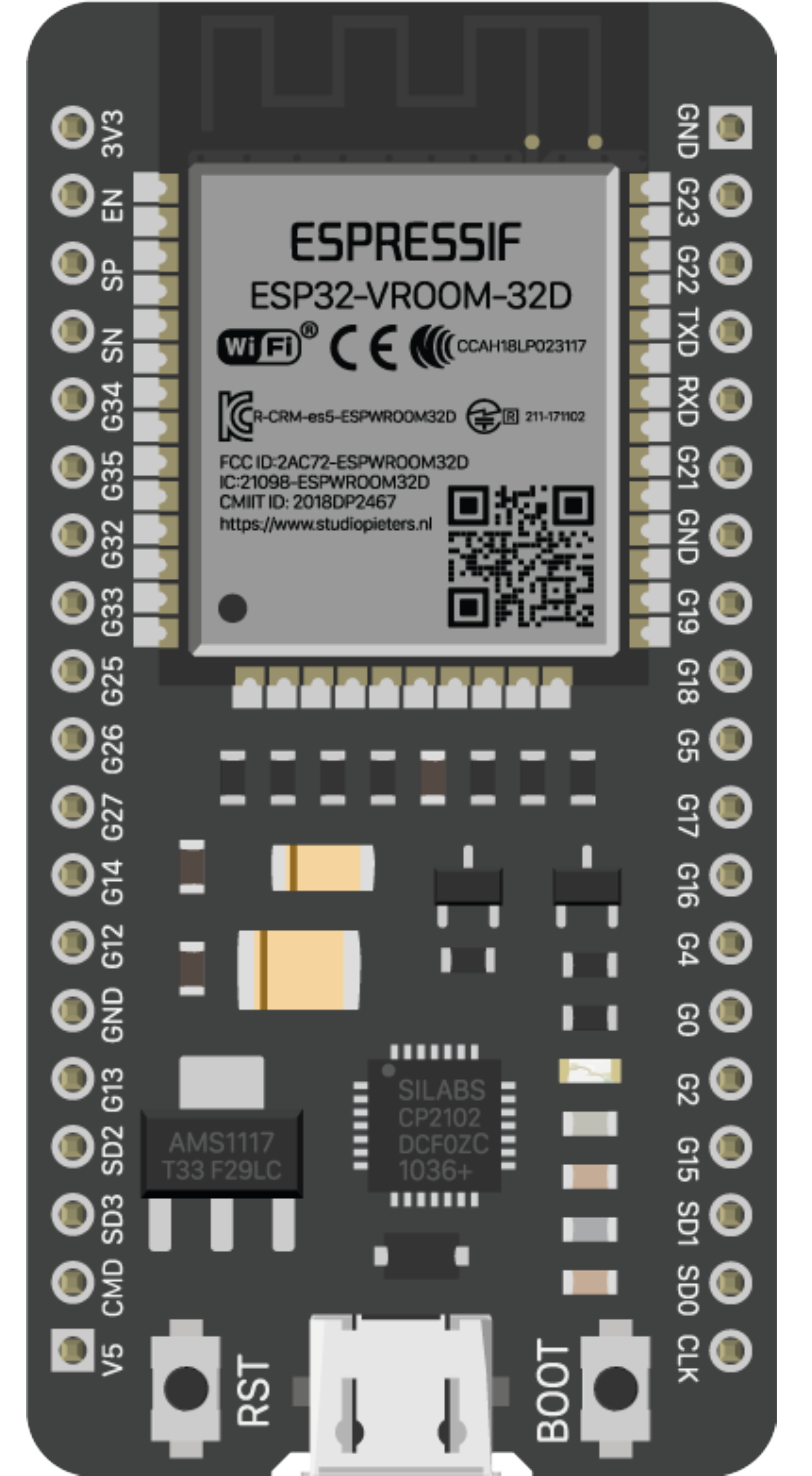
The ESP32-38 PINS, manufactured by Espressif Systems (Part ID: ESP32-WROOM-32), is a highly versatile microcontroller with 38 GPIO (General Purpose Input/Output) pins. These pins support a wide range of functionalities, including digital input/output, analog input, PWM output, and communication protocols such as I2C, SPI, and UART. The ESP32 is widely used in IoT, embedded systems, and smart devices due to its powerful dual-core processor, integrated Wi-Fi, and Bluetooth capabilities.
Explore Projects Built with ESP32-38 PINS


Explore Projects Built with ESP32-38 PINS
Common Applications
- IoT devices and smart home automation
- Wireless sensor networks
- Robotics and motor control
- Wearable devices
- Data logging and monitoring systems
- Industrial automation
Technical Specifications
Key Technical Details
| Parameter | Specification |
|---|---|
| Manufacturer | Espressif Systems |
| Part ID | ESP32-WROOM-32 |
| Operating Voltage | 3.3V |
| Input Voltage Range | 2.2V - 3.6V |
| GPIO Pins | 38 |
| Wi-Fi Standard | 802.11 b/g/n |
| Bluetooth Version | v4.2 BR/EDR and BLE |
| Flash Memory | 4MB (default, varies by model) |
| SRAM | 520KB |
| Clock Speed | Up to 240 MHz |
| ADC Channels | 18 (12-bit resolution) |
| DAC Channels | 2 |
| Communication Protocols | UART, SPI, I2C, I2S, CAN, PWM |
| Operating Temperature | -40°C to +85°C |
Pin Configuration and Descriptions
The ESP32-38 PINS module features 38 GPIO pins, each capable of multiple functions. Below is a summary of the pin configuration:
| Pin Number | Pin Name | Functionality |
|---|---|---|
| 1 | EN | Enable pin (active high) |
| 2 | IO0 | GPIO0, boot mode selection |
| 3 | IO1 (TX0) | GPIO1, UART0 TX |
| 4 | IO2 | GPIO2, PWM, ADC, DAC |
| 5 | IO3 (RX0) | GPIO3, UART0 RX |
| 6 | IO4 | GPIO4, PWM, ADC |
| 7 | IO5 | GPIO5, PWM, ADC |
| 8 | IO12 | GPIO12, ADC, SPI |
| 9 | IO13 | GPIO13, ADC, SPI |
| 10 | IO14 | GPIO14, ADC, SPI |
| 11 | IO15 | GPIO15, ADC, SPI |
| 12 | IO16 | GPIO16, UART2 RX |
| 13 | IO17 | GPIO17, UART2 TX |
| 14 | IO18 | GPIO18, SPI SCK |
| 15 | IO19 | GPIO19, SPI MISO |
| 16 | IO21 | GPIO21, I2C SDA |
| 17 | IO22 | GPIO22, I2C SCL |
| 18 | IO23 | GPIO23, SPI MOSI |
| 19 | IO25 | GPIO25, ADC, DAC |
| 20 | IO26 | GPIO26, ADC, DAC |
| 21 | IO27 | GPIO27, ADC |
| 22 | IO32 | GPIO32, ADC |
| 23 | IO33 | GPIO33, ADC |
| 24 | IO34 | GPIO34, ADC (input only) |
| 25 | IO35 | GPIO35, ADC (input only) |
| 26 | IO36 | GPIO36, ADC (input only) |
| 27 | IO39 | GPIO39, ADC (input only) |
Note: Some GPIO pins have specific restrictions or are input-only. Refer to the ESP32 datasheet for detailed electrical characteristics.
Usage Instructions
How to Use the ESP32-38 PINS in a Circuit
- Power Supply: Connect the ESP32 to a 3.3V power source. Avoid exceeding the maximum input voltage of 3.6V to prevent damage.
- GPIO Configuration: Use the GPIO pins for digital input/output, analog input, or communication protocols. Configure the pins in your code as needed.
- Programming: The ESP32 can be programmed using the Arduino IDE, ESP-IDF, or other compatible environments. Use a USB-to-serial converter for uploading code.
- Wi-Fi and Bluetooth: Initialize the Wi-Fi or Bluetooth modules in your code to enable wireless communication.
Important Considerations
- Voltage Levels: Ensure all connected peripherals operate at 3.3V logic levels. Use level shifters if interfacing with 5V devices.
- Boot Mode: GPIO0 must be pulled low during boot to enter programming mode.
- Current Consumption: The ESP32 can draw significant current during Wi-Fi or Bluetooth operation. Use a power supply capable of providing at least 500mA.
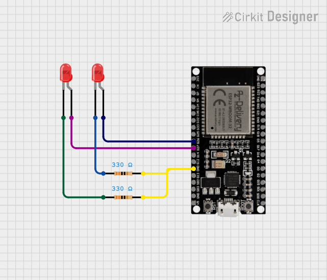
Example Code for Arduino UNO
Below is an example of using the ESP32 to blink an LED connected to GPIO2:
// Define the GPIO pin for the LED
#define LED_PIN 2

void setup() {
  pinMode(LED_PIN, OUTPUT); // Set GPIO2 as an output pin
}

void loop() {
  digitalWrite(LED_PIN, HIGH); // Turn the LED on
  delay(1000);                 // Wait for 1 second
  digitalWrite(LED_PIN, LOW);  // Turn the LED off
  delay(1000);                 // Wait for 1 second
}
Tip: Use the Serial Monitor in the Arduino IDE to debug your code and monitor outputs.
Troubleshooting and FAQs
Common Issues
ESP32 Not Detected by Computer:
- Ensure the correct USB driver is installed for your USB-to-serial converter.
- Check the USB cable for data transfer capability (some cables are power-only).
Code Upload Fails:
- Verify that GPIO0 is pulled low during programming.
- Check the selected board and COM port in the Arduino IDE.
Wi-Fi Connection Issues:
- Ensure the correct SSID and password are used in your code.
- Check for interference or weak signal strength.
Overheating:
- Avoid overloading the GPIO pins or exceeding the maximum current ratings.
- Use proper heat dissipation techniques if operating in high-temperature environments.
FAQs
Q: Can I use the ESP32 with 5V peripherals?
A: The ESP32 operates at 3.3V logic levels. Use level shifters to interface with 5V peripherals.
Q: How do I reset the ESP32?
A: Press the EN (Enable) button on the module to reset the ESP32.
Q: Can I use all GPIO pins simultaneously?
A: Not all GPIO pins can be used simultaneously due to internal restrictions and shared functionalities. Refer to the ESP32 datasheet for details.
Q: What is the maximum current output of a GPIO pin?
A: Each GPIO pin can source or sink up to 12mA. For higher currents, use external drivers or transistors.
By following this documentation, you can effectively utilize the ESP32-38 PINS module in your projects. For further details, consult the official Espressif Systems datasheet and reference materials.