How to Use Step Up Boost Power Converter, Adjustable Voltage Regulator: Examples, Pinouts, and Specs
Introduction
The Youmile Step Up Boost Power Converter is a versatile and efficient DC-DC voltage regulator designed to step up a lower input voltage to a higher, adjustable output voltage. This component is widely used in applications requiring stable and adjustable power supply, such as battery-powered devices, DIY electronics projects, and portable power systems. Its compact design and high efficiency make it an excellent choice for hobbyists and professionals alike.
Explore Projects Built with Step Up Boost Power Converter, Adjustable Voltage Regulator


Explore Projects Built with Step Up Boost Power Converter, Adjustable Voltage Regulator
Common Applications and Use Cases
- Powering devices requiring higher voltage from a lower voltage source (e.g., 5V to 12V).
- Battery-powered systems, such as lithium-ion or AA battery packs.
- DIY electronics projects, including Arduino-based systems.
- LED lighting systems and small motor drivers.
- Portable power banks and USB-powered devices.
Technical Specifications
The following table outlines the key technical details of the Youmile Step Up Boost Power Converter:
| Parameter | Specification |
|---|---|
| Input Voltage Range | 3V to 35V DC |
| Output Voltage Range | 4V to 40V DC (adjustable) |
| Maximum Output Current | 2A (continuous), 3A (peak) |
| Efficiency | Up to 92% (depending on input/output) |
| Switching Frequency | 150 kHz |
| Operating Temperature | -40°C to +85°C |
| Dimensions | 43mm x 21mm x 14mm |
Pin Configuration and Descriptions
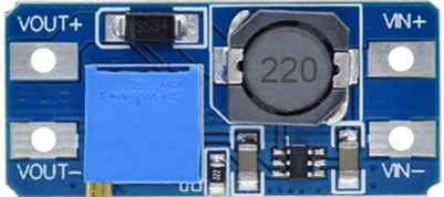
The module has four main pins for input and output connections:
| Pin Name | Description |
|---|---|
| VIN+ | Positive input voltage terminal (3V to 35V DC). |
| VIN- | Negative input voltage terminal (ground). |
| VOUT+ | Positive output voltage terminal (4V to 40V DC). |
| VOUT- | Negative output voltage terminal (ground). |
Usage Instructions
How to Use the Component in a Circuit
Connect the Input Voltage:
- Attach the positive terminal of your power source to the
VIN+pin. - Connect the negative terminal of your power source to the
VIN-pin.
- Attach the positive terminal of your power source to the
Connect the Output Load:
- Attach the positive terminal of your load (e.g., motor, LED, or circuit) to the
VOUT+pin. - Connect the negative terminal of your load to the
VOUT-pin.
- Attach the positive terminal of your load (e.g., motor, LED, or circuit) to the
Adjust the Output Voltage:
- Use a small screwdriver to turn the onboard potentiometer (blue trimmer).
- Turn clockwise to increase the output voltage or counterclockwise to decrease it.
- Measure the output voltage with a multimeter to ensure it matches your desired value.
Power On:
- Once all connections are secure, power on the input source. The module will regulate the input voltage to the desired output voltage.
Important Considerations and Best Practices
- Input Voltage Limit: Ensure the input voltage does not exceed 35V to avoid damaging the module.
- Output Voltage Adjustment: Always adjust the output voltage without a load connected to prevent overvoltage damage to your components.
- Heat Dissipation: For high current applications, consider adding a heatsink to the module to prevent overheating.
- Polarity Protection: Double-check the polarity of your connections to avoid short circuits or damage.
- Load Current: Do not exceed the maximum continuous current rating of 2A to ensure stable operation.
Example: Using with an Arduino UNO
The Step Up Boost Power Converter can be used to power an Arduino UNO from a lower voltage source, such as a 3.7V lithium-ion battery. Below is an example circuit and code:
Circuit Connections
- Connect the battery's positive terminal to
VIN+and negative terminal toVIN-. - Adjust the output voltage to 7.5V (recommended for Arduino UNO).
- Connect
VOUT+to the Arduino's VIN pin andVOUT-to the Arduino's GND pin.
Example Code
// Example code to blink an LED connected to Arduino UNO
// Ensure the Step Up Boost Converter is providing 7.5V to the Arduino VIN pin.

const int ledPin = 13; // Built-in LED pin on Arduino UNO

void setup() {
  pinMode(ledPin, OUTPUT); // Set LED pin as output
}

void loop() {
  digitalWrite(ledPin, HIGH); // Turn the LED on
  delay(1000);                // Wait for 1 second
  digitalWrite(ledPin, LOW);  // Turn the LED off
  delay(1000);                // Wait for 1 second
}
Troubleshooting and FAQs
Common Issues and Solutions
No Output Voltage:
- Cause: Incorrect input connections or insufficient input voltage.
- Solution: Verify the polarity and ensure the input voltage is within the 3V to 35V range.
Output Voltage Not Adjustable:
- Cause: Faulty potentiometer or incorrect adjustment.
- Solution: Turn the potentiometer slowly and ensure no load is connected during adjustment.
Overheating:
- Cause: Excessive current draw or poor ventilation.
- Solution: Reduce the load current or add a heatsink to the module.
Output Voltage Drops Under Load:
- Cause: Input voltage too low or load exceeds current rating.
- Solution: Increase the input voltage or reduce the load current.
FAQs
Q: Can this module step down voltage as well?
A: No, this is a boost converter and can only step up voltage.Q: Is the module protected against reverse polarity?
A: No, reverse polarity can damage the module. Always double-check connections.Q: Can I use this module to charge batteries?
A: While possible, it is not recommended unless you have additional circuitry to manage charging safely.Q: What is the maximum efficiency I can expect?
A: The module can achieve up to 92% efficiency, depending on the input and output voltage difference.
By following this documentation, you can effectively integrate the Youmile Step Up Boost Power Converter into your projects and troubleshoot common issues with ease.