
How to Use MPU9250/GY -91: Examples, Pinouts, and Specs
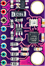
 Design with MPU9250/GY -91 in Cirkit Designer
Introduction
The MPU9250/GY-91 is a 9-axis motion tracking device that integrates a 3-axis gyroscope, a 3-axis accelerometer, and a 3-axis magnetometer into a single compact module. This sensor is widely used in applications requiring precise orientation and motion sensing, such as robotics, drones, mobile devices, and wearable technology. Its ability to measure angular velocity, linear acceleration, and magnetic field strength makes it a versatile component for motion tracking and navigation systems.
Explore Projects Built with MPU9250/GY -91
 Open Project in Cirkit Designer
 Open Project in Cirkit Designer
 Open Project in Cirkit Designer
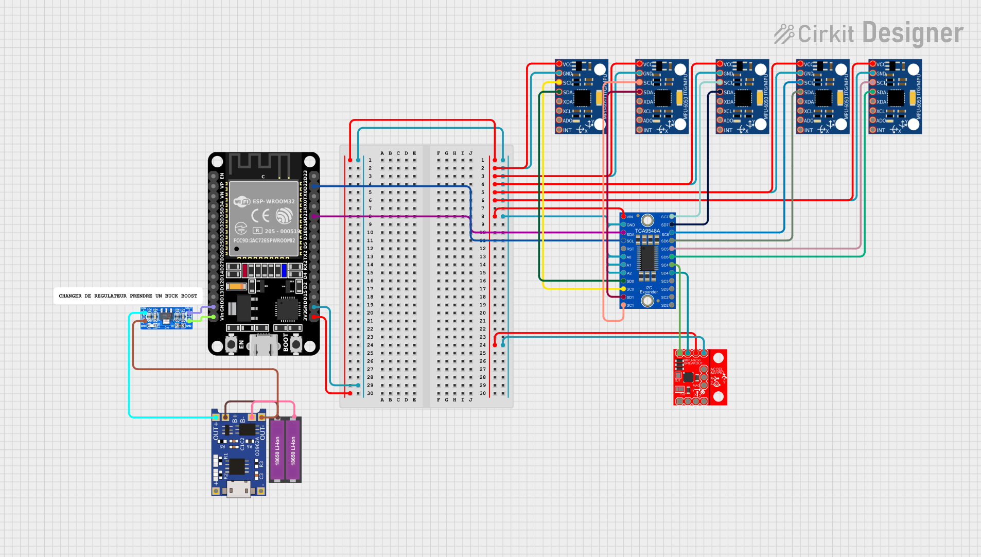 Open Project in Cirkit Designer
Explore Projects Built with MPU9250/GY -91
Open Project in Cirkit DesignerOpen Project in Cirkit DesignerOpen Project in Cirkit DesignerOpen Project in Cirkit DesignerTechnical Specifications
Key Technical Details
- Gyroscope Range: ±250, ±500, ±1000, ±2000 degrees/second
- Accelerometer Range: ±2g, ±4g, ±8g, ±16g
- Magnetometer Range: ±4800 µT
- Communication Protocols: I2C (up to 400 kHz), SPI (up to 1 MHz)
- Operating Voltage: 2.4V to 3.6V (typically 3.3V)
- Current Consumption:
- Gyroscope: 3.2 mA
- Accelerometer: 450 µA
- Magnetometer: 280 µA
- Operating Temperature: -40°C to +85°C
- Package Dimensions: 3x3x1 mm (MPU9250 IC), varies for GY-91 breakout board
Pin Configuration and Descriptions
The GY-91 breakout board typically has the following pinout:
| Pin | Name | Description |
|---|---|---|
| 1 | VCC | Power supply input (3.3V recommended) |
| 2 | GND | Ground connection |
| 3 | SCL | I2C clock line (or SPI clock line in SPI mode) |
| 4 | SDA | I2C data line (or SPI data input/output in SPI mode) |
| 5 | NCS | Chip select for SPI communication (active low, connect to GND for I2C mode) |
| 6 | INT | Interrupt pin (used for motion detection or data-ready signals) |
| 7 | AD0/SDO | I2C address selection (connect to GND for 0x68 or VCC for 0x69) / SPI data out |
Usage Instructions
How to Use the MPU9250/GY-91 in a Circuit
- Power the Module: Connect the VCC pin to a 3.3V power source and GND to ground.
- Select Communication Protocol:
- For I2C: Connect the SCL and SDA pins to the corresponding I2C pins on your microcontroller. Ensure the NCS pin is connected to GND.
- For SPI: Connect the SCL, SDA, NCS, and AD0/SDO pins to the appropriate SPI pins on your microcontroller.
- Set the I2C Address: If using I2C, connect the AD0 pin to GND for the default address (0x68) or to VCC for the alternate address (0x69).
- Add Pull-Up Resistors: If not already present on the breakout board, add 4.7kΩ pull-up resistors to the SCL and SDA lines for I2C communication.
- Initialize the Sensor: Use a library or write custom code to configure the sensor and read data.
Important Considerations and Best Practices
- Voltage Levels: Ensure the microcontroller's logic levels are compatible with the 3.3V logic of the MPU9250/GY-91. Use a level shifter if necessary.
- Magnetometer Calibration: Perform a calibration routine to account for hard and soft iron distortions in the magnetic field.
- Mounting Orientation: Secure the module firmly to minimize vibrations and ensure accurate readings.
- Interrupt Usage: Use the INT pin for applications requiring real-time motion detection or data-ready signals.
Example Code for Arduino UNO
Below is an example of how to use the MPU9250/GY-91 with an Arduino UNO via I2C:
#include <Wire.h>
#include <MPU9250.h> // Include a library for MPU9250 (e.g., SparkFun MPU-9250 library)

MPU9250 mpu; // Create an MPU9250 object

void setup() {
  Serial.begin(9600); // Initialize serial communication
  Wire.begin();       // Initialize I2C communication

  // Initialize the MPU9250
  if (mpu.begin() != INV_SUCCESS) {
    Serial.println("Failed to initialize MPU9250!");
    while (1); // Halt if initialization fails
  }
  Serial.println("MPU9250 initialized successfully!");
}

void loop() {
  // Read sensor data
  if (mpu.readSensor() == INV_SUCCESS) {
    Serial.print("Accel (g): ");
    Serial.print(mpu.getAccelX_mss(), 2); Serial.print(", ");
    Serial.print(mpu.getAccelY_mss(), 2); Serial.print(", ");
    Serial.println(mpu.getAccelZ_mss(), 2);

    Serial.print("Gyro (deg/s): ");
    Serial.print(mpu.getGyroX_rads(), 2); Serial.print(", ");
    Serial.print(mpu.getGyroY_rads(), 2); Serial.print(", ");
    Serial.println(mpu.getGyroZ_rads(), 2);

    Serial.print("Mag (uT): ");
    Serial.print(mpu.getMagX_uT(), 2); Serial.print(", ");
    Serial.print(mpu.getMagY_uT(), 2); Serial.print(", ");
    Serial.println(mpu.getMagZ_uT(), 2);

    delay(500); // Delay for readability
  } else {
    Serial.println("Failed to read sensor data!");
  }
}
Troubleshooting and FAQs
Common Issues
No Communication with the Sensor:
- Cause: Incorrect wiring or I2C address mismatch.
- Solution: Double-check the connections and ensure the AD0 pin is set correctly for the desired I2C address.
Inaccurate Readings:
- Cause: Lack of calibration or external interference.
- Solution: Perform accelerometer, gyroscope, and magnetometer calibration. Avoid placing the sensor near magnetic or metallic objects.
Sensor Not Initializing:
- Cause: Incorrect power supply voltage or faulty module.
- Solution: Verify the power supply voltage is 3.3V. Test with another module if necessary.
FAQs
Q: Can the MPU9250/GY-91 be powered with 5V?
A: No, the module operates at 3.3V. Use a voltage regulator or level shifter if interfacing with a 5V system.Q: How do I calibrate the magnetometer?
A: Rotate the sensor in all directions while collecting data, then use a calibration algorithm to compute offsets and scaling factors.Q: Can I use SPI and I2C simultaneously?
A: No, the module supports either SPI or I2C, but not both at the same time. Select one protocol based on your application.Q: What is the maximum sampling rate?
A: The MPU9250 supports a maximum sampling rate of 1 kHz for the gyroscope and accelerometer.