The SIM7600G-H is a 4G LTE module manufactured by SIMCOM. It supports a wide range of communication protocols, including GSM, GPRS, HSPA+, and LTE, making it a versatile solution for IoT applications. This module is designed to provide high-speed data transmission, voice communication, and GPS functionality, making it ideal for applications such as remote monitoring, smart metering, vehicle tracking, and industrial automation.
Explore Projects Built with SIM7600G-H
Use Cirkit Designer to design, explore, and prototype these projects online. Some projects support real-time simulation. Click "Open Project" to start designing instantly!
This circuit features an Arduino Mega 2560 microcontroller interfaced with a SIM800L GSM module, two fingerprint scanners, an I2C LCD display, an IR sensor, and a piezo buzzer. Power management is handled by a PowerBoost 1000 Basic Pad USB, a TP4056 charging module, and a Li-ion 18650 battery, with an option to use a Mini AC-DC 110V-230V to 5V 700mA module for direct power supply. The primary functionality appears to be a security system with GSM communication capabilities, biometric access control, and visual/audible feedback.
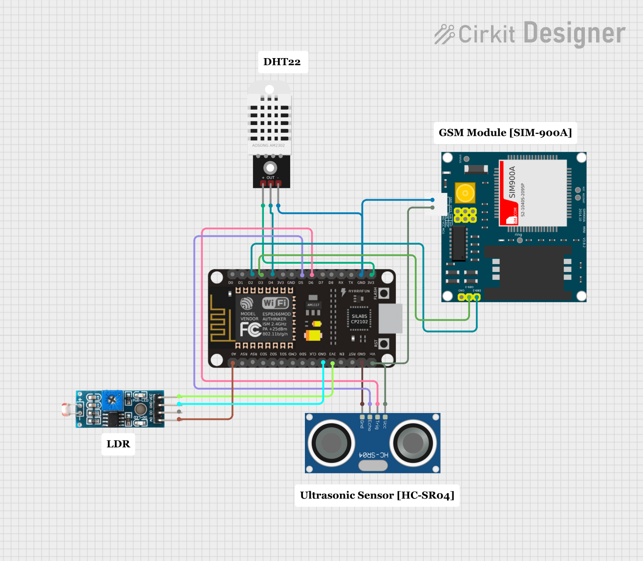
This is a sensor-based data acquisition system with GSM communication capability. It uses an ESP8266 NodeMCU to collect environmental data from a DHT22 sensor and light levels from an LDR, as well as distance measurements from an HC-SR04 ultrasonic sensor. The SIM900A GSM module enables the system to transmit the collected data over a cellular network.
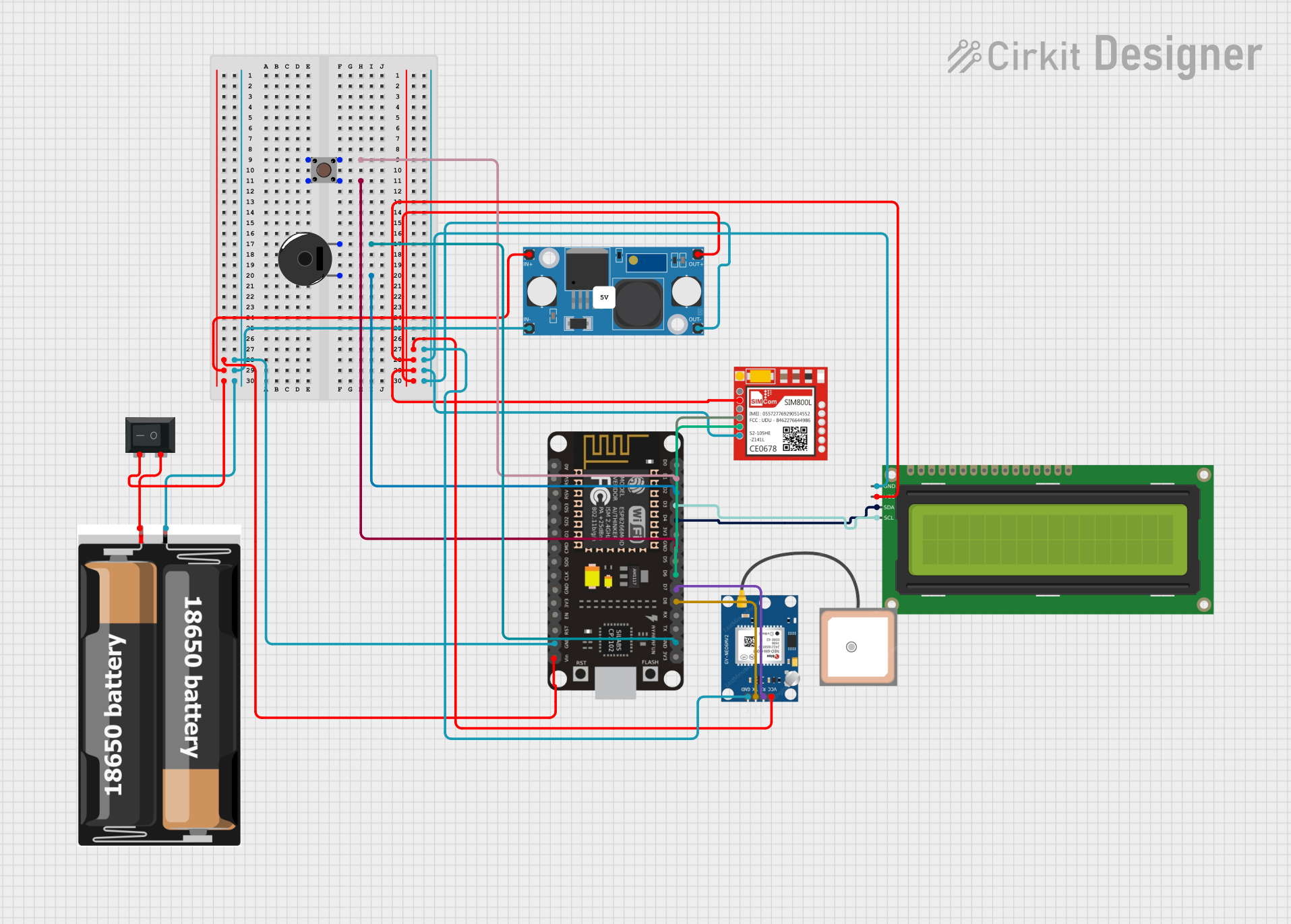
This circuit integrates an ESP8266 NodeMCU microcontroller with a SIM800L GSM module, a GPS NEO 6M module, and a 16x2 I2C LCD display for communication and location tracking. It also includes a pushbutton for user input, a piezo buzzer for audio alerts, and is powered by a 2x 18650 battery pack through an LM2596 step-down module.
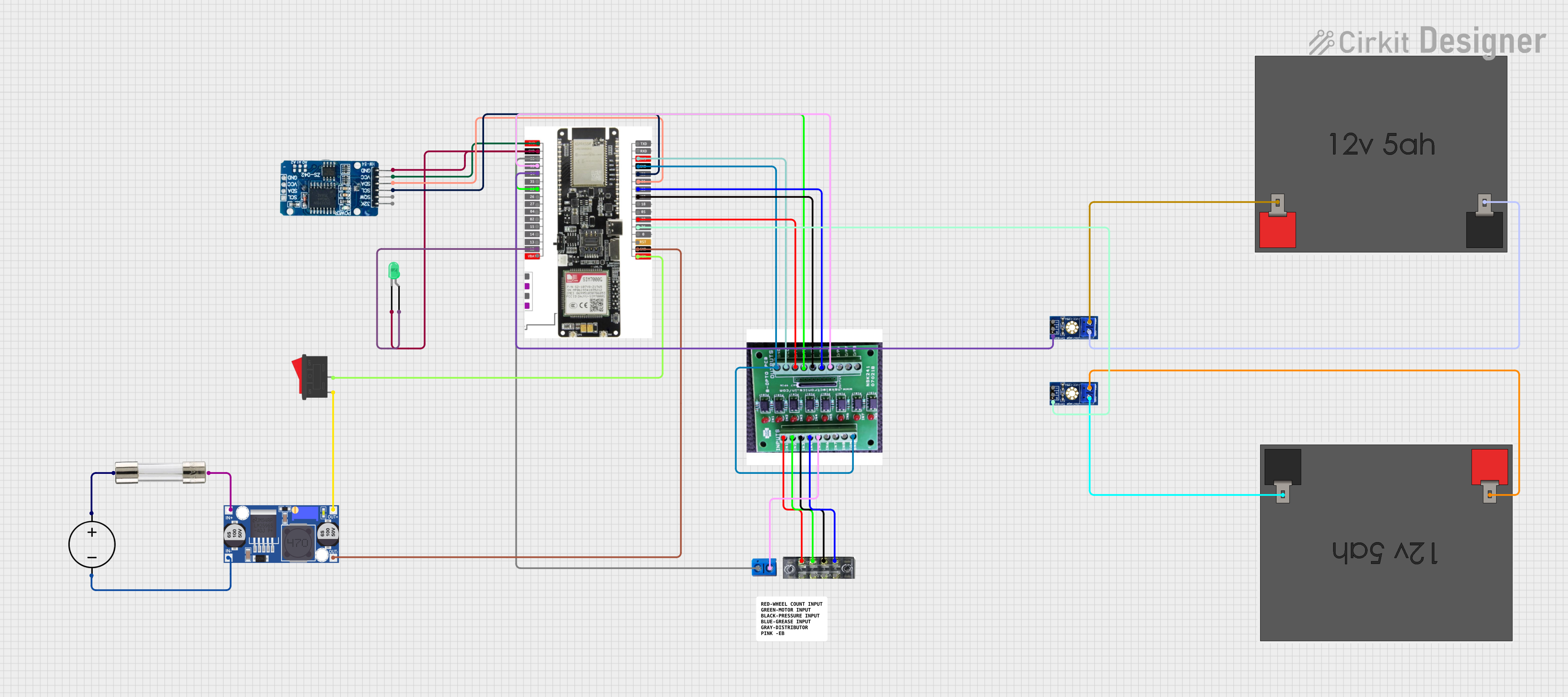
This circuit features a LilyGo-SIM7000G module for cellular communication and GPS functionality, interfaced with an RTC DS3231 for real-time clock capabilities. It includes voltage sensing through two voltage sensor modules, and uses an 8-channel opto-coupler for isolating different parts of the circuit. Power management is handled by a buck converter connected to a DC power source and batteries, with a fuse for protection and a rocker switch for on/off control. Additionally, there's an LED for indication purposes.
Idle: ~1.5mA, Active: ~500mA (varies with network conditions)
Operating Temperature
-40°C to +85°C
Dimensions
30.0mm x 30.0mm x 2.9mm
Interface
UART, USB 2.0, I2C, GPIO, ADC, PCM
Antenna Interfaces
Main Antenna, GNSS Antenna
Certifications
CE, FCC, RoHS, PTCRB, GCF
Pin Configuration and Descriptions
The SIM7600G-H module has multiple pins for communication and power. Below is a summary of the key pins:
Pin Number
Pin Name
Description
1
VCC
Power supply input (3.4V to 4.2V).
2
GND
Ground connection.
3
TXD
UART Transmit Data (for serial communication).
4
RXD
UART Receive Data (for serial communication).
5
USB_D+
USB differential data line (positive).
6
USB_D-
USB differential data line (negative).
7
GNSS_TXD
GNSS UART Transmit Data.
8
GNSS_RXD
GNSS UART Receive Data.
9
RESET
Reset pin (active low).
10
PWRKEY
Power-on key (active low, hold for 1 second to power on/off).
11
ADC_IN
Analog-to-Digital Converter input.
12
GPIO1
General-purpose input/output pin.
Usage Instructions
How to Use the SIM7600G-H in a Circuit
Power Supply: Connect the VCC pin to a stable power source (3.4V to 4.2V) and the GND pin to ground.
Serial Communication: Use the TXD and RXD pins for UART communication with a microcontroller or PC.
USB Interface: Connect the USB_D+ and USB_D- pins to a USB port for data transfer or firmware updates.
Antenna Connections: Attach a 4G LTE antenna to the Main Antenna port and a GPS antenna to the GNSS Antenna port for optimal performance.
Power On/Off: Use the PWRKEY pin to turn the module on or off. Hold the pin low for at least 1 second to toggle the power state.
Reset: If needed, use the RESET pin to restart the module.
Important Considerations and Best Practices
Power Supply: Ensure a stable power supply with minimal noise to avoid communication issues.
Antenna Placement: Place antennas away from high-frequency noise sources for better signal quality.
Firmware Updates: Regularly update the module's firmware to ensure compatibility with the latest networks.
Heat Management: If used in high-temperature environments, ensure proper ventilation or heat dissipation.
Example: Connecting SIM7600G-H to Arduino UNO
Below is an example of how to connect the SIM7600G-H to an Arduino UNO and send an SMS:
Wiring
SIM7600G-H Pin
Arduino UNO Pin
VCC
5V (via a voltage regulator)
GND
GND
TXD
Pin 10 (RX)
RXD
Pin 11 (TX)
PWRKEY
Digital Pin 9
Code
#include <SoftwareSerial.h>

// Define RX and TX pins for SoftwareSerial
SoftwareSerial sim7600(10, 11); // RX = Pin 10, TX = Pin 11

#define PWRKEY 9 // Power key pin

void setup() {
  pinMode(PWRKEY, OUTPUT);
  digitalWrite(PWRKEY, LOW); // Ensure PWRKEY is low initially
  delay(1000);
  digitalWrite(PWRKEY, HIGH); // Power on the SIM7600G-H
  delay(2000);
  digitalWrite(PWRKEY, LOW); // Release PWRKEY

  sim7600.begin(9600); // Start communication with SIM7600G-H
  Serial.begin(9600);  // Start communication with PC
  Serial.println("Initializing SIM7600G-H...");

  sendCommand("AT"); // Test AT command
  sendCommand("AT+CMGF=1"); // Set SMS mode to text
  sendCommand("AT+CMGS=\"+1234567890\""); // Replace with recipient's phone number
  sim7600.print("Hello from SIM7600G-H!"); // SMS content
  sim7600.write(26); // Send SMS (Ctrl+Z)
}

void loop() {
  if (sim7600.available()) {
    Serial.write(sim7600.read()); // Forward SIM7600G-H responses to Serial Monitor
  }
}

void sendCommand(String command) {
  sim7600.println(command);
  delay(1000); // Wait for the command to execute
}
Troubleshooting and FAQs
Common Issues and Solutions
Module Not Powering On
Ensure the VCC pin is receiving a stable voltage between 3.4V and 4.2V.
Check the PWRKEY pin connection and ensure it is held low for at least 1 second.
No Response to AT Commands
Verify the UART connections (TXD and RXD) between the module and the microcontroller.
Ensure the baud rate matches the module's default (9600 bps).
Poor Signal Quality
Check the antenna connections and ensure they are securely attached.
Place the antennas in an open area away from interference.
GPS Not Working
Ensure the GNSS antenna is connected and placed in an open area with a clear view of the sky.
Wait for a few minutes for the module to acquire satellite signals.
FAQs
Q: Can the SIM7600G-H be powered directly from a 5V source? A: No, the module requires a voltage between 3.4V and 4.2V. Use a voltage regulator if necessary.
Q: How do I update the firmware? A: Use the USB interface to connect the module to a PC and follow the manufacturer's firmware update instructions.
Q: What is the maximum data rate supported by the module? A: The SIM7600G-H supports LTE Cat-4 with a maximum downlink speed of 150 Mbps and uplink speed of 50 Mbps.
This concludes the documentation for the SIM7600G-H module. For further details, refer to the official datasheet provided by SIMCOM.



 Open Project in Cirkit Designer