How to Use KUONGSHUN ESP32-CAM: Examples, Pinouts, and Specs
Introduction
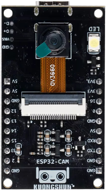
The KUONGSHUN ESP32-CAM is a low-cost development board designed for IoT applications. It features an ESP32 microcontroller with integrated Wi-Fi and Bluetooth capabilities, along with a built-in OV2640 camera module. This versatile board is ideal for projects requiring image capture, video streaming, or wireless communication. Its compact size and powerful features make it a popular choice for smart home devices, surveillance systems, and AI-based applications.
Explore Projects Built with KUONGSHUN ESP32-CAM


Explore Projects Built with KUONGSHUN ESP32-CAM
Common Applications:
- Wireless video streaming and surveillance
- Smart home automation
- Face recognition and object detection
- IoT-enabled image processing
- Remote monitoring systems
Technical Specifications
Key Technical Details:
| Parameter | Specification |
|---|---|
| Microcontroller | ESP32-D0WDQ6 |
| Wireless Connectivity | Wi-Fi 802.11 b/g/n, Bluetooth 4.2 |
| Camera Module | OV2640 |
| Flash Memory | 4 MB (PSRAM) |
| Operating Voltage | 3.3V |
| Input Voltage Range | 5V (via micro-USB or external source) |
| GPIO Pins | 9 (configurable for various functions) |
| Image Resolution | Up to 1600x1200 (UXGA) |
| Dimensions | 27mm x 40.5mm |
Pin Configuration and Descriptions:
| Pin Name | Pin Number | Description |
|---|---|---|
| GND | 1 | Ground connection |
| 3.3V | 2 | 3.3V power supply output |
| IO0 | 3 | GPIO0, used for boot mode selection (connect to GND for programming mode) |
| IO2 | 4 | GPIO2, used for general-purpose I/O or camera functions |
| IO4 | 5 | GPIO4, general-purpose I/O |
| IO12 | 6 | GPIO12, general-purpose I/O |
| IO13 | 7 | GPIO13, general-purpose I/O |
| IO14 | 8 | GPIO14, general-purpose I/O |
| IO15 | 9 | GPIO15, general-purpose I/O |
| IO16 | 10 | GPIO16, general-purpose I/O |
| IO33 | 11 | GPIO33, general-purpose I/O |
| RXD | 12 | UART RX pin for serial communication |
| TXD | 13 | UART TX pin for serial communication |
| RESET | 14 | Reset pin, used to restart the board |
Usage Instructions
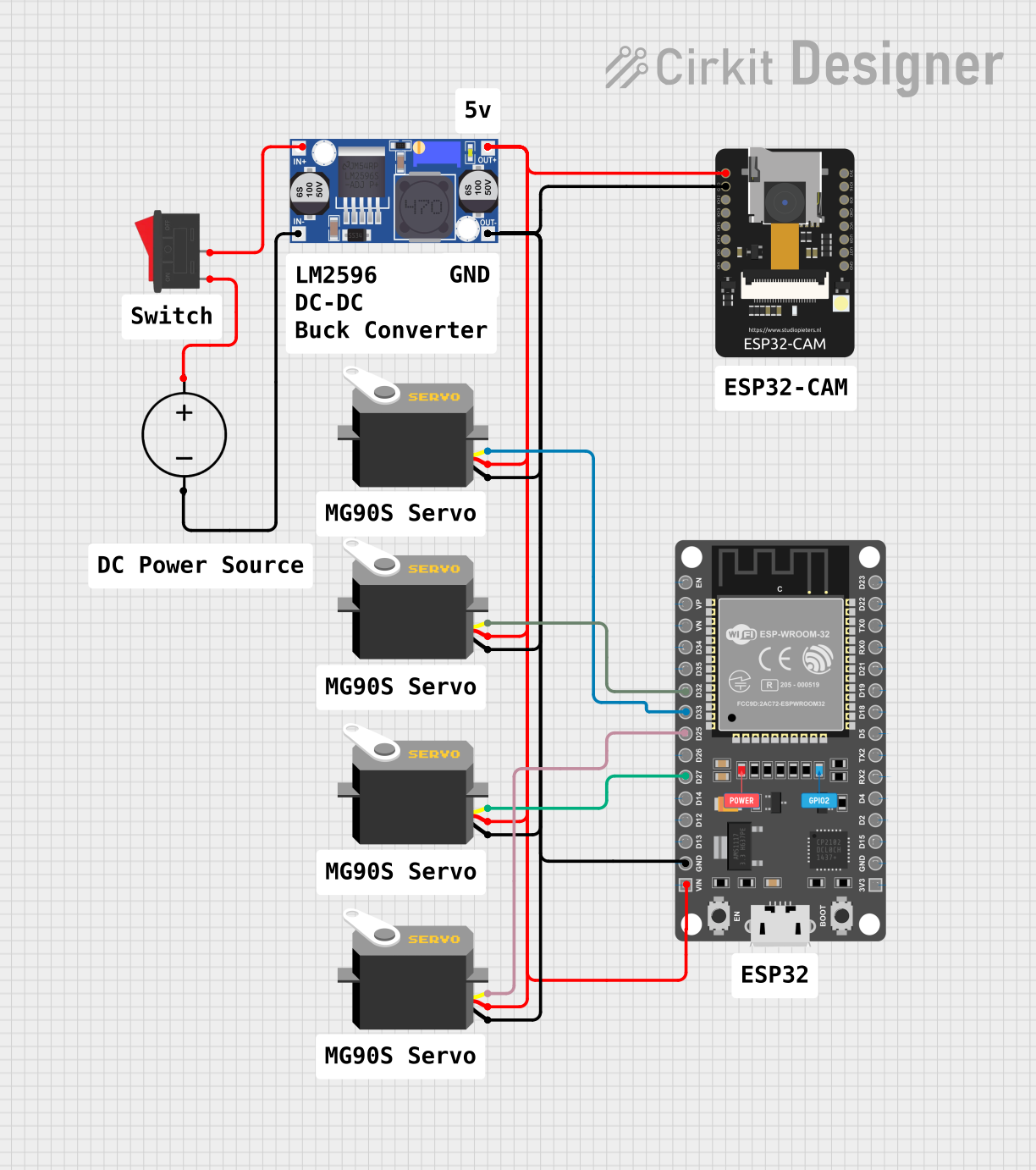
How to Use the KUONGSHUN ESP32-CAM in a Circuit:
Powering the Board:
- Supply 5V to the board via the micro-USB port or an external power source.
- Ensure the power source can provide at least 500mA of current for stable operation.
Programming the Board:
- Connect the ESP32-CAM to your computer using a USB-to-TTL serial adapter.
- Connect the adapter's TX pin to the ESP32-CAM's RXD pin and the RX pin to the TXD pin.
- Short GPIO0 to GND to enable programming mode.
- Use the Arduino IDE or other supported environments to upload your code.
Connecting the Camera:
- The OV2640 camera module is pre-installed. Ensure it is securely connected to the board.
- Use the provided libraries (e.g., ESP32 Camera library) to initialize and control the camera.
Wi-Fi and Bluetooth Setup:
- Configure the Wi-Fi credentials in your code to connect the ESP32-CAM to a network.
- Use Bluetooth for additional communication if required.
Important Considerations and Best Practices:
- Heat Management: The ESP32-CAM can get warm during operation. Ensure proper ventilation.
- Power Supply: Use a stable 5V power source to avoid unexpected resets or malfunctions.
- Antenna Placement: For optimal Wi-Fi performance, ensure the onboard antenna is not obstructed.
- Boot Mode: Always disconnect GPIO0 from GND after programming to boot into normal mode.
- Camera Handling: Avoid touching the camera lens to prevent smudges or damage.
Example Code for Arduino UNO:
Below is an example of how to use the ESP32-CAM to capture and stream video:
#include "esp_camera.h"
#include <WiFi.h>

// Replace with your network credentials
const char* ssid = "Your_SSID";
const char* password = "Your_PASSWORD";

// Camera configuration
#define PWDN_GPIO_NUM    -1
#define RESET_GPIO_NUM   -1
#define XCLK_GPIO_NUM     0
#define SIOD_GPIO_NUM    26
#define SIOC_GPIO_NUM    27
#define Y9_GPIO_NUM      35
#define Y8_GPIO_NUM      34
#define Y7_GPIO_NUM      39
#define Y6_GPIO_NUM      36
#define Y5_GPIO_NUM      21
#define Y4_GPIO_NUM      19
#define Y3_GPIO_NUM      18
#define Y2_GPIO_NUM       5
#define VSYNC_GPIO_NUM   25
#define HREF_GPIO_NUM    23
#define PCLK_GPIO_NUM    22

void startCameraServer();

void setup() {
  Serial.begin(115200);
  WiFi.begin(ssid, password);

  // Wait for Wi-Fi connection
  while (WiFi.status() != WL_CONNECTED) {
    delay(500);
    Serial.print(".");
  }
  Serial.println("");
  Serial.println("WiFi connected");

  // Camera initialization
  camera_config_t config;
  config.ledc_channel = LEDC_CHANNEL_0;
  config.ledc_timer = LEDC_TIMER_0;
  config.pin_d0 = Y2_GPIO_NUM;
  config.pin_d1 = Y3_GPIO_NUM;
  config.pin_d2 = Y4_GPIO_NUM;
  config.pin_d3 = Y5_GPIO_NUM;
  config.pin_d4 = Y6_GPIO_NUM;
  config.pin_d5 = Y7_GPIO_NUM;
  config.pin_d6 = Y8_GPIO_NUM;
  config.pin_d7 = Y9_GPIO_NUM;
  config.pin_xclk = XCLK_GPIO_NUM;
  config.pin_pclk = PCLK_GPIO_NUM;
  config.pin_vsync = VSYNC_GPIO_NUM;
  config.pin_href = HREF_GPIO_NUM;
  config.pin_sscb_sda = SIOD_GPIO_NUM;
  config.pin_sscb_scl = SIOC_GPIO_NUM;
  config.pin_pwdn = PWDN_GPIO_NUM;
  config.pin_reset = RESET_GPIO_NUM;
  config.xclk_freq_hz = 20000000;
  config.pixel_format = PIXFORMAT_JPEG;

  if (psramFound()) {
    config.frame_size = FRAMESIZE_UXGA;
    config.jpeg_quality = 10;
    config.fb_count = 2;
  } else {
    config.frame_size = FRAMESIZE_SVGA;
    config.jpeg_quality = 12;
    config.fb_count = 1;
  }

  // Initialize the camera
  esp_err_t err = esp_camera_init(&config);
  if (err != ESP_OK) {
    Serial.printf("Camera init failed with error 0x%x", err);
    return;
  }

  // Start the camera server
  startCameraServer();
  Serial.println("Camera ready! Use 'http://<ESP32-CAM-IP>' to view the stream.");
}

void loop() {
  // Main loop does nothing; camera server handles everything
}
Troubleshooting and FAQs
Common Issues and Solutions:
ESP32-CAM Not Detected by Computer:
- Ensure the USB-to-TTL adapter is properly connected.
- Verify that GPIO0 is connected to GND during programming.
Wi-Fi Connection Fails:
- Double-check the SSID and password in your code.
- Ensure the Wi-Fi network is within range and not overloaded.
Camera Initialization Fails:
- Verify that the camera module is securely connected.
- Check the power supply for stability.
Overheating:
- Provide adequate ventilation or use a small heatsink if necessary.
FAQs:
Can I use the ESP32-CAM without a camera?
Yes, the ESP32-CAM can function as a standard ESP32 development board for other IoT applications.What is the maximum supported image resolution?
The OV2640 camera supports up to 1600x1200 (UXGA) resolution.Can I power the ESP32-CAM with 3.3V?
No, the recommended input voltage is 5V for stable operation.