How to Use 12V solenoid lock: Examples, Pinouts, and Specs
Introduction
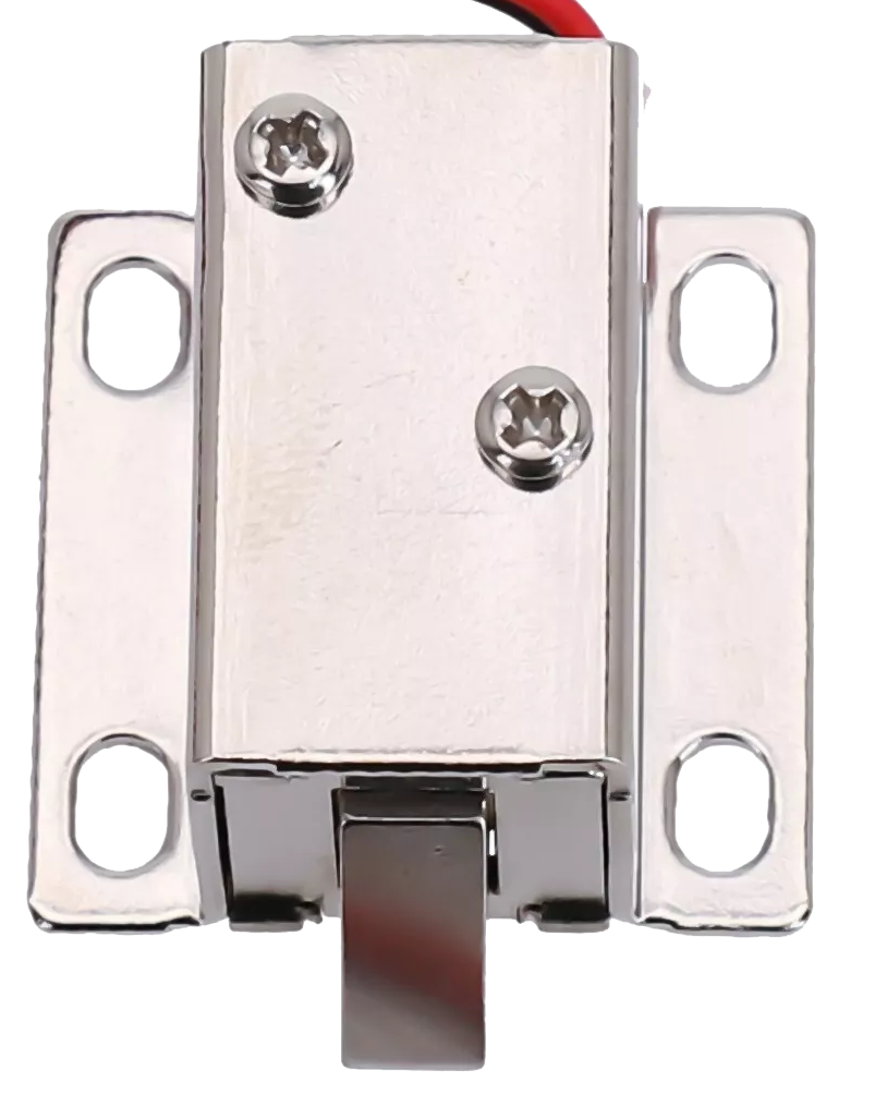
A 12V solenoid lock is an electronic locking device that utilizes a solenoid—a coil of wire that becomes magnetized when electricity flows through it—to actuate a locking mechanism. These locks are widely used in access control systems, vending machines, safety deposit boxes, and various DIY projects where electronic control of a locking mechanism is desired. When 12 volts of power is applied, the solenoid actuates to either lock or unlock, making it a versatile component for security and automation applications.
Explore Projects Built with 12V solenoid lock
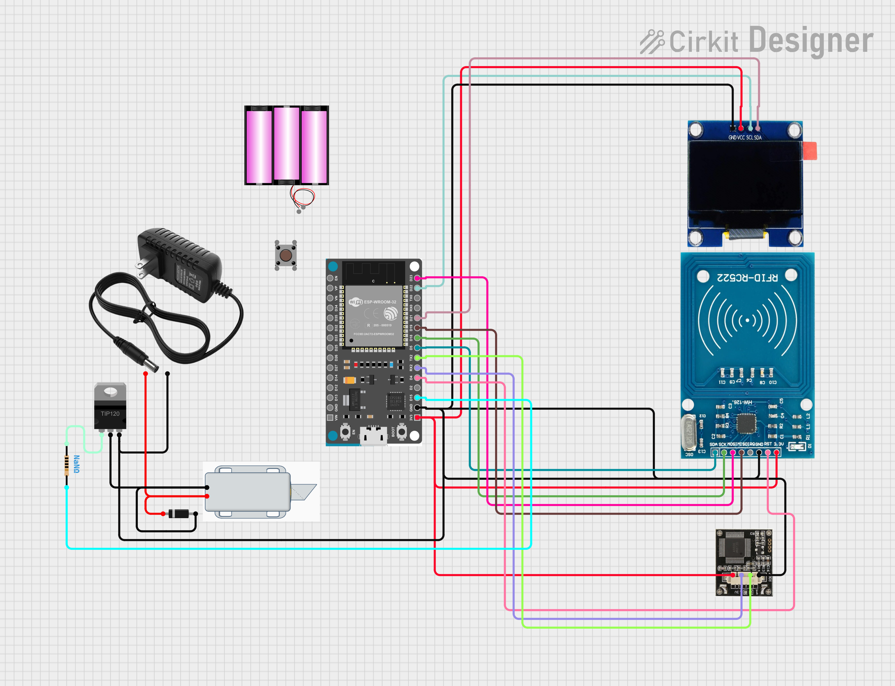
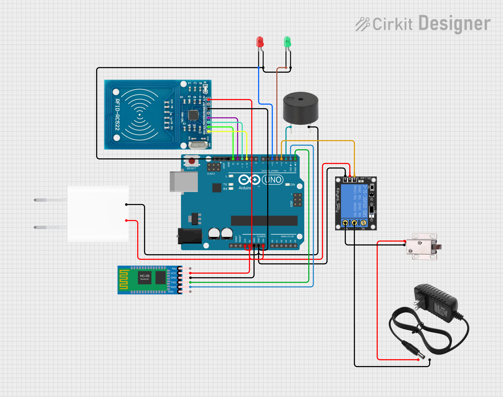
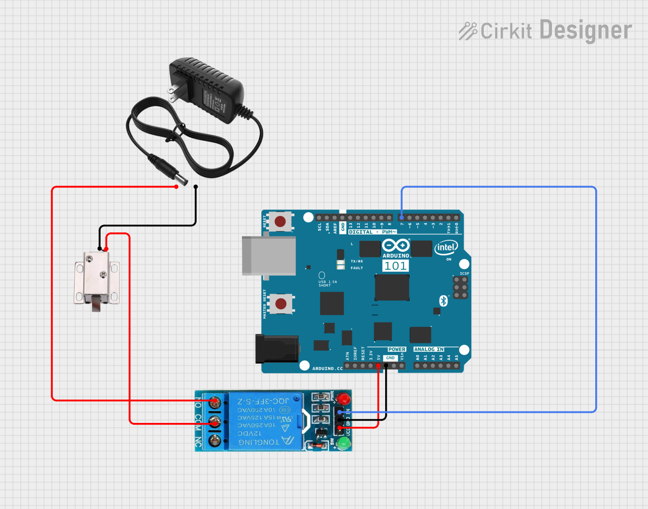
Explore Projects Built with 12V solenoid lock
Technical Specifications
General Features
- Operating Voltage: 12V DC
- Current Draw: 1A to 2A (at 12V DC during actuation)
- Power Consumption: 12W to 24W (during actuation)
- Operation Mode: Fail-safe or Fail-secure (depending on model)
- Actuation Time: Typically less than 1 second
- Duty Cycle: Intermittent use recommended (not for continuous operation)
Pin Configuration and Descriptions
| Pin Number | Description | Notes |
|---|---|---|
| 1 | Positive Voltage (V+) | Connect to 12V DC power supply |
| 2 | Ground (GND) | Connect to system ground |
Usage Instructions
Connecting to a Circuit
- Power Supply: Ensure that the power supply is capable of delivering 12V DC and can handle the current draw of the solenoid lock (1A to 2A).
- Wiring: Connect the positive terminal of the power supply to Pin 1 (V+) and the negative terminal to Pin 2 (GND).
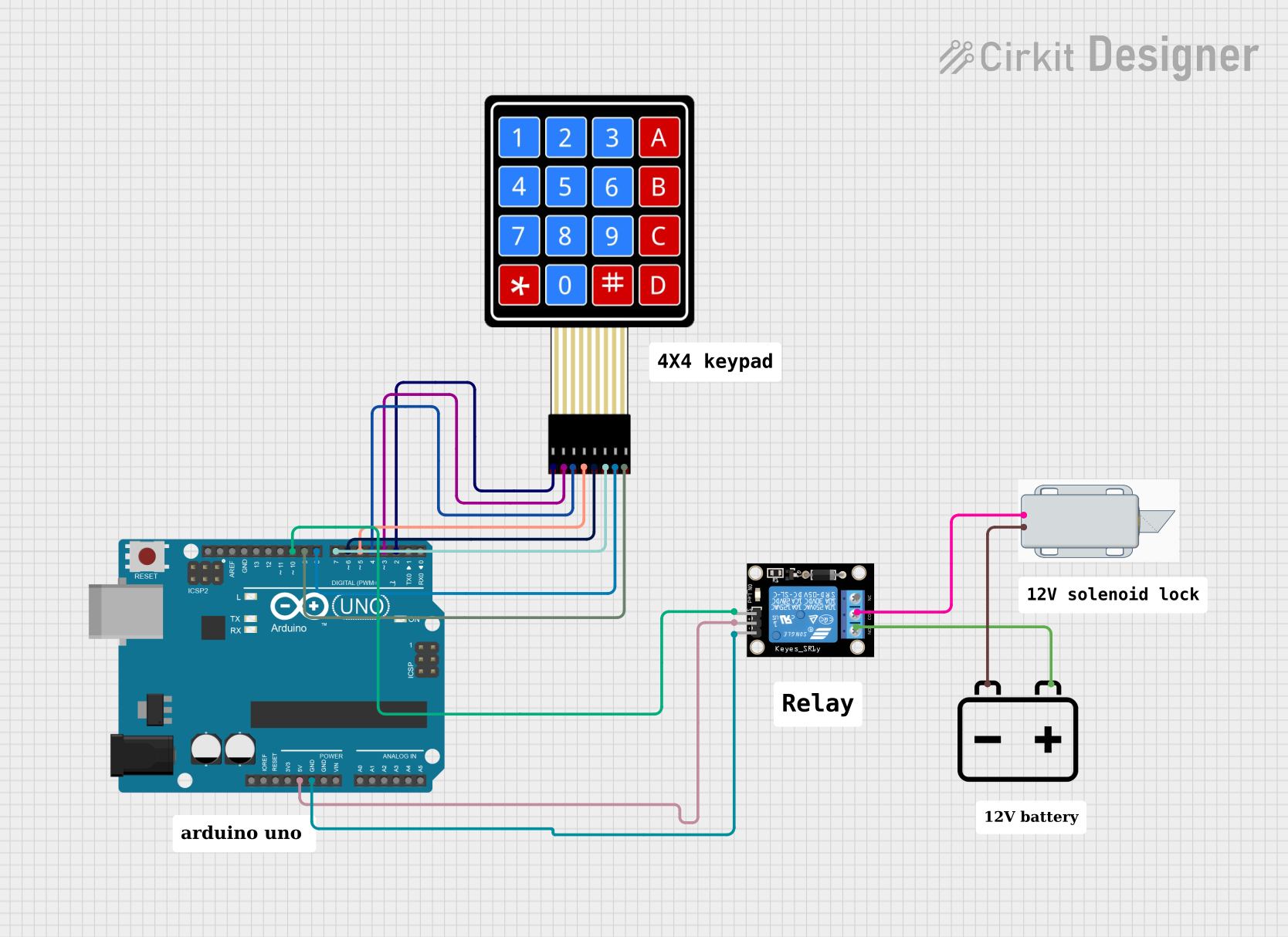
- Control: To control the solenoid lock, use a relay or a transistor that can handle the current requirements. This will allow you to switch the power to the solenoid lock on and off using a microcontroller like an Arduino UNO.
Best Practices
- Intermittent Use: The solenoid lock is not designed for continuous use. To prevent overheating, it should be actuated only for short periods.
- Heat Dissipation: Ensure that there is adequate ventilation around the solenoid lock to dissipate heat during operation.
- Protective Diode: Place a flyback diode across the solenoid coil to prevent voltage spikes when the solenoid is de-energized.
Example Arduino UNO Code
// Define the pin connected to the relay or transistor controlling the solenoid
const int solenoidPin = 7;

void setup() {
  pinMode(solenoidPin, OUTPUT); // Set the solenoid pin as an output
}

void loop() {
  digitalWrite(solenoidPin, HIGH); // Activate the solenoid lock
  delay(1000); // Keep the solenoid lock activated for 1 second
  digitalWrite(solenoidPin, LOW); // Deactivate the solenoid lock
  delay(5000); // Wait for 5 seconds before next activation
}
Troubleshooting and FAQs
Common Issues
Solenoid Lock Does Not Actuate:
- Check the power supply for proper voltage and current.
- Ensure that the wiring connections are secure.
- Verify that the control circuit (relay or transistor) is functioning correctly.
Solenoid Overheats:
- Reduce the actuation time.
- Increase the cooling or ventilation around the solenoid lock.
Solenoid Lock Sticks in Position:
- Lubricate the moving parts if accessible.
- Check for mechanical obstructions or misalignment.
FAQs
Q: Can I power the solenoid lock directly from an Arduino pin? A: No, an Arduino pin cannot supply enough current. Use a relay or transistor.
Q: How long can I keep the solenoid lock activated? A: It is designed for intermittent use. Keep activation time as short as possible.
Q: What is the purpose of the flyback diode? A: The diode protects the control circuit from voltage spikes when the solenoid is turned off.
Q: Can the solenoid lock be used outdoors? A: Unless specified by the manufacturer, it is designed for indoor use. Check for weatherproof models for outdoor applications.
For further assistance, consult the manufacturer's datasheet or contact technical support.