
How to Use ULN2003A breakout board: Examples, Pinouts, and Specs
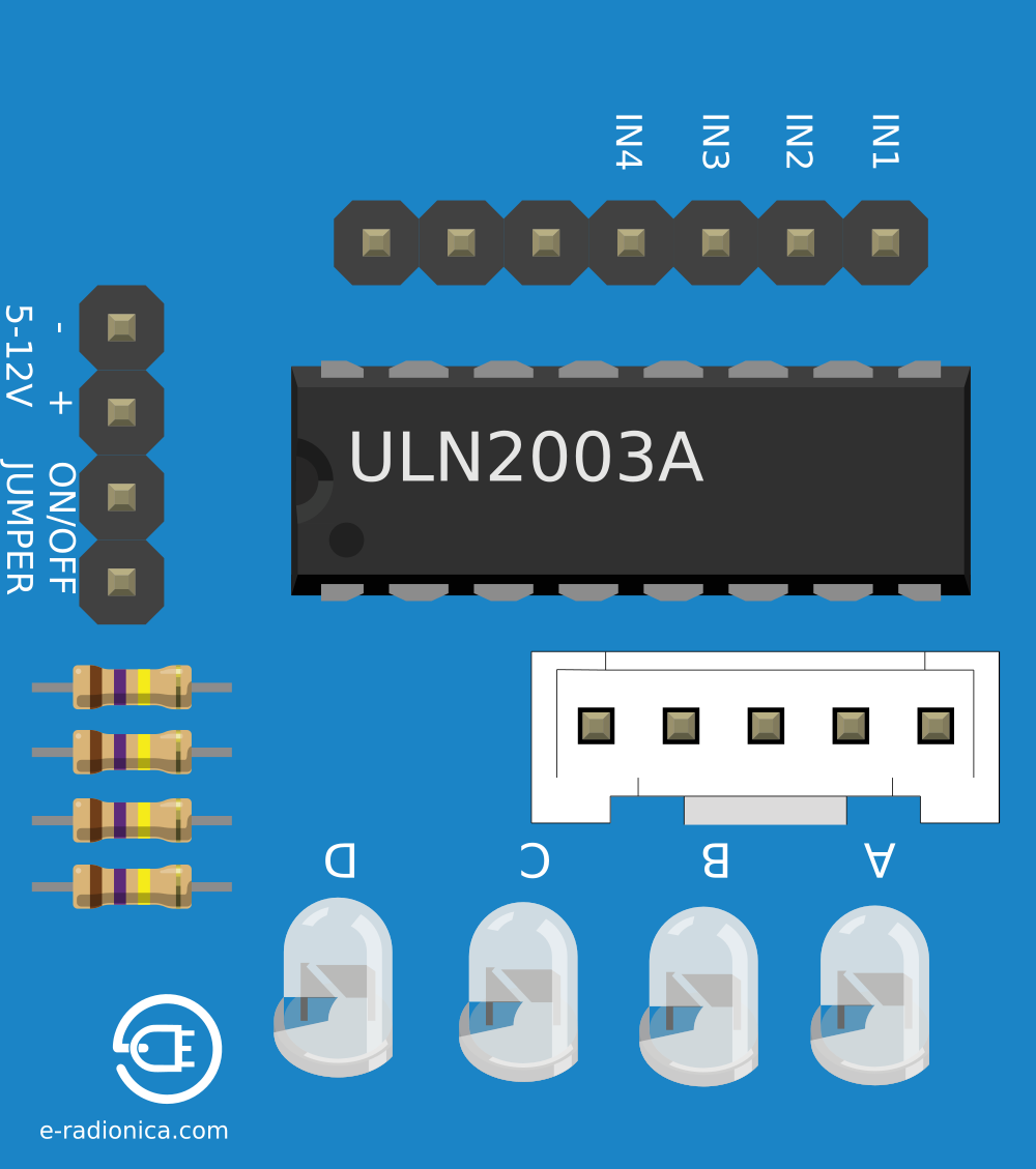
 Design with ULN2003A breakout board in Cirkit Designer
Introduction
The ULN2003A breakout board is a compact circuit board that integrates the ULN2003A IC, a high-voltage, high-current Darlington transistor array. This board is designed to simplify the process of driving inductive loads such as stepper motors, relays, solenoids, and lamps. It acts as an interface between low-power control signals (e.g., from a microcontroller) and high-power devices, enabling efficient and reliable operation.
Explore Projects Built with ULN2003A breakout board
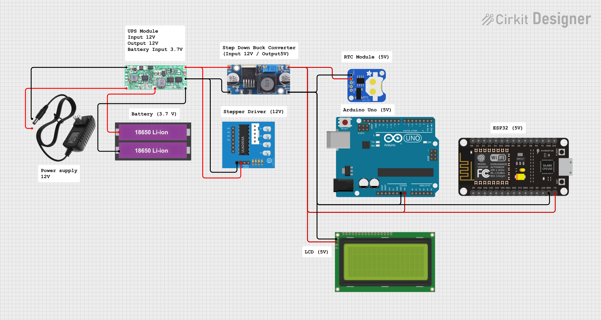 Open Project in Cirkit Designer
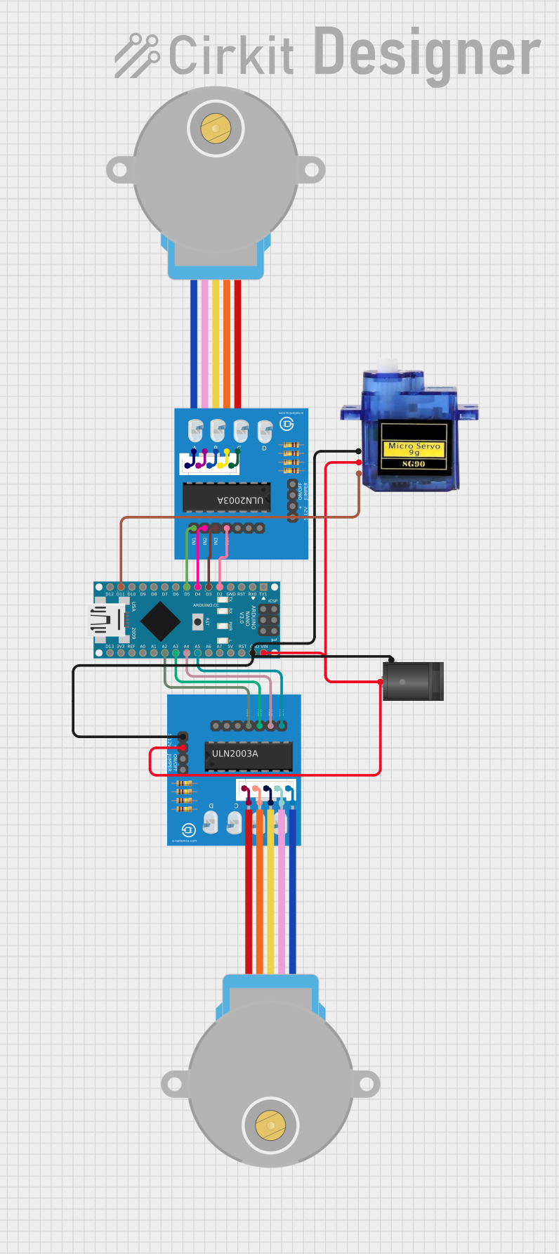 Open Project in Cirkit Designer
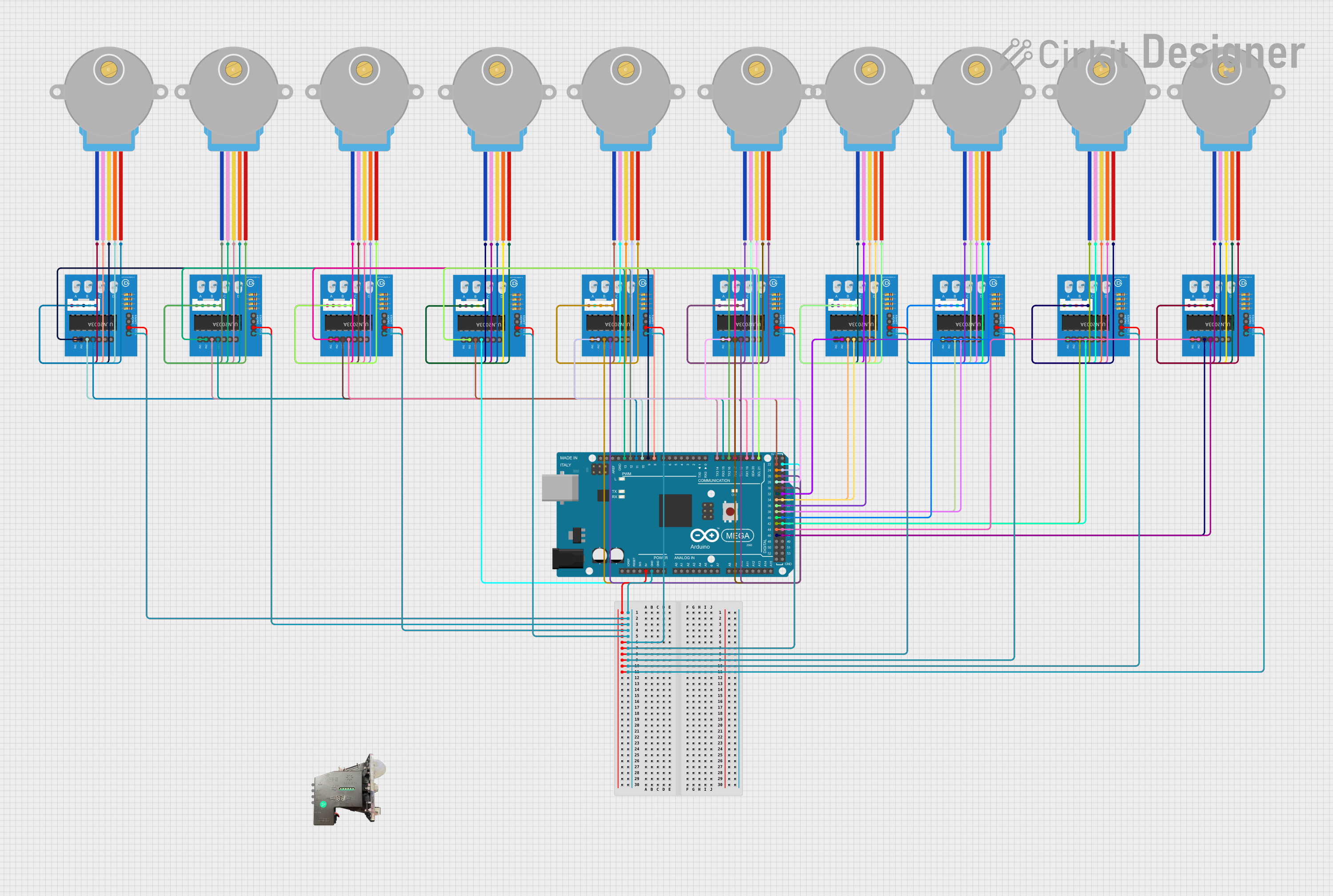 Open Project in Cirkit Designer
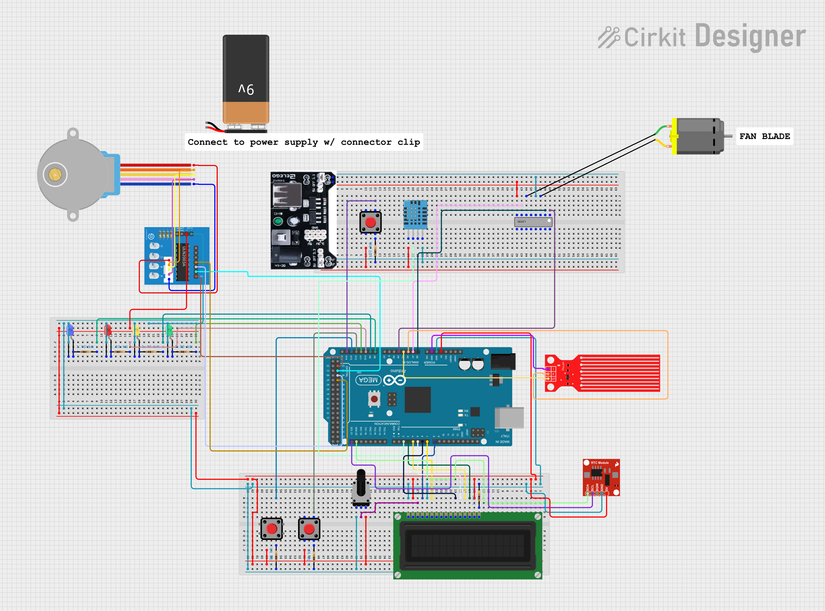 Open Project in Cirkit Designer
Explore Projects Built with ULN2003A breakout board
Open Project in Cirkit DesignerOpen Project in Cirkit DesignerOpen Project in Cirkit DesignerOpen Project in Cirkit DesignerCommon Applications and Use Cases
- Driving stepper motors in robotics and automation systems
- Controlling relays in home automation or industrial applications
- Switching solenoids in vending machines or locking mechanisms
- Powering high-current LEDs or lamps
- Any application requiring the control of high-power devices with low-power signals
Technical Specifications
Key Technical Details
- IC Model: ULN2003A
- Number of Channels: 7 (independent Darlington transistor pairs)
- Input Voltage (Logic): 2.7V to 5V (TTL/CMOS compatible)
- Output Voltage: Up to 50V
- Output Current (Per Channel): Up to 500mA
- Maximum Total Current: 2.5A (shared across all channels)
- Integrated Flyback Diodes: Protects against voltage spikes from inductive loads
- Board Dimensions: Typically 40mm x 20mm (may vary by manufacturer)
- Connector Type: 10-pin header for inputs and outputs, motor-specific connectors (e.g., 4-pin for stepper motors)
Pin Configuration and Descriptions
The ULN2003A breakout board typically features a 10-pin header for input and output connections, along with a motor-specific connector. Below is the pin configuration:
Input/Control Pins
| Pin Number | Pin Name | Description |
|---|---|---|
| 1 | IN1 | Input for Channel 1 |
| 2 | IN2 | Input for Channel 2 |
| 3 | IN3 | Input for Channel 3 |
| 4 | IN4 | Input for Channel 4 |
| 5 | IN5 | Input for Channel 5 |
| 6 | IN6 | Input for Channel 6 |
| 7 | IN7 | Input for Channel 7 |
| 8 | GND | Ground (common ground for logic and power) |
| 9 | VCC | Logic voltage supply (typically 5V) |
| 10 | COM | Common cathode for flyback diodes (connect to load power supply) |
Output Pins
| Pin Number | Pin Name | Description |
|---|---|---|
| 1 | OUT1 | Output for Channel 1 |
| 2 | OUT2 | Output for Channel 2 |
| 3 | OUT3 | Output for Channel 3 |
| 4 | OUT4 | Output for Channel 4 |
| 5 | OUT5 | Output for Channel 5 |
| 6 | OUT6 | Output for Channel 6 |
| 7 | OUT7 | Output for Channel 7 |
Usage Instructions
How to Use the Component in a Circuit
- Power the Board: Connect the VCC pin to a 5V power supply and the GND pin to the ground.
- Connect the Load: Attach the load (e.g., motor, relay, or lamp) to the output pins (OUT1–OUT7). Ensure the load's power supply is connected to the COM pin.
- Control Signals: Connect the input pins (IN1–IN7) to the control signals from a microcontroller or other logic device. A HIGH signal (logic 1) on an input pin activates the corresponding output channel.
- Flyback Diode Protection: The board includes integrated flyback diodes to protect against voltage spikes from inductive loads. Ensure the COM pin is connected to the load's power supply for proper operation.
Important Considerations and Best Practices
- Current Limitations: Do not exceed 500mA per channel or 2.5A total across all channels to avoid damaging the IC.
- Heat Dissipation: If driving high-current loads, consider adding a heatsink or ensuring adequate ventilation to prevent overheating.
- Logic Compatibility: Ensure the input signals are within the acceptable voltage range (2.7V–5V).
- Power Supply: Use a stable and adequately rated power supply for both the logic and load circuits.
- Stepper Motor Use: When driving stepper motors, connect the motor's 4-pin connector to the dedicated motor header on the breakout board.
Example: Using with Arduino UNO
Below is an example of controlling a stepper motor using the ULN2003A breakout board and an Arduino UNO:
// Include the Arduino Stepper library
#include <Stepper.h>

// Define the number of steps per revolution for your motor
#define STEPS_PER_REV 2048

// Initialize the Stepper library with the motor pins
// Connect IN1, IN2, IN3, IN4 to Arduino pins 8, 9, 10, 11
Stepper stepper(STEPS_PER_REV, 8, 10, 9, 11);

void setup() {
  // Set the motor speed (in RPM)
  stepper.setSpeed(15);
  // Initialize serial communication for debugging
  Serial.begin(9600);
  Serial.println("Stepper Motor Control Initialized");
}

void loop() {
  // Rotate the motor one full revolution clockwise
  Serial.println("Rotating clockwise...");
  stepper.step(STEPS_PER_REV);
  delay(1000); // Wait for 1 second

  // Rotate the motor one full revolution counterclockwise
  Serial.println("Rotating counterclockwise...");
  stepper.step(-STEPS_PER_REV);
  delay(1000); // Wait for 1 second
}
Troubleshooting and FAQs
Common Issues and Solutions
No Output on the Load
- Cause: Incorrect wiring or missing power supply.
- Solution: Verify all connections, ensure the VCC and COM pins are powered, and check the input signals.
Overheating of the IC
- Cause: Exceeding the current limits or inadequate ventilation.
- Solution: Reduce the load current, ensure proper heat dissipation, or add a heatsink.
Stepper Motor Not Rotating Properly
- Cause: Incorrect wiring or step sequence.
- Solution: Double-check the motor connections and ensure the correct step sequence is used in the code.
Voltage Spikes Damaging Components
- Cause: COM pin not connected to the load power supply.
- Solution: Ensure the COM pin is properly connected to the load's power supply to enable flyback diode protection.
FAQs
Can I use the ULN2003A breakout board with a 3.3V microcontroller?
- Yes, the ULN2003A is compatible with 3.3V logic levels, but ensure the input voltage is within the specified range.
What types of motors can I drive with this board?
- The board is suitable for unipolar stepper motors, DC motors, and other inductive loads.
Do I need external diodes for inductive loads?
- No, the ULN2003A includes integrated flyback diodes for this purpose.
Can I control all 7 channels simultaneously?
- Yes, but ensure the total current does not exceed 2.5A to avoid damaging the IC.