Cirkit Designer Logo
Cirkit Designer
Your all-in-one circuit design IDE
Home / 
Component Documentation

How to Use 2 Channel G3MB-202P Solid-State Relay: Examples, Pinouts, and Specs

Image of 2 Channel G3MB-202P Solid-State Relay
Cirkit Designer LogoDesign with 2 Channel G3MB-202P Solid-State Relay in Cirkit Designer

Introduction

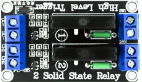
The 2 Channel G3MB-202P Solid-State Relay (SSR) is an electronic switching device that enables control of high power devices using low power signals. Unlike mechanical relays, the G3MB-202P SSR uses semiconductor devices, providing silent operation, fast switching speeds, and increased reliability. This component is commonly used in automation systems, microcontroller projects, and situations where precise control of high voltage/current loads is required.

Explore Projects Built with 2 Channel G3MB-202P Solid-State Relay

Use Cirkit Designer to design, explore, and prototype these projects online. Some projects support real-time simulation. Click "Open Project" to start designing instantly!
ESP32 Wi-Fi Controlled Dual Relay Module
Image of esp: A project utilizing 2 Channel G3MB-202P Solid-State Relay in a practical application
This circuit features an ESP32 microcontroller connected to a two-channel 5V relay module. The ESP32 controls the relay channels via its GPIO pins D23 and D22, allowing it to switch external devices on and off. The relay module is powered by the 3.3V and GND pins of the ESP32.
Cirkit Designer LogoOpen Project in Cirkit Designer
Battery-Powered 4-Channel Relay Control with LED Indicators
Image of RELLAY BOARD TEST: A project utilizing 2 Channel G3MB-202P Solid-State Relay in a practical application
This circuit consists of a 5V battery powering a 4-channel relay module, which controls four LEDs (red, yellow, green, and blue) through individual resistors. Each relay channel is activated by a corresponding SPST toggle switch, allowing manual control of the LEDs.
Cirkit Designer LogoOpen Project in Cirkit Designer
ESP32-Powered 8-Channel Relay Controller with Wi-Fi Connectivity
Image of Olimex ESP32-POE2 4Ch X 2 Switches: A project utilizing 2 Channel G3MB-202P Solid-State Relay in a practical application
This circuit features an ESP32 microcontroller connected to an 8-channel relay module. The ESP32 controls the relay channels via its GPIO pins, allowing for the switching of external devices or loads through the relays.
Cirkit Designer LogoOpen Project in Cirkit Designer
Wi-Fi Controlled Relay System with ESP32 and LED Indicators
Image of GIZMO_CONTROL_ONLY: A project utilizing 2 Channel G3MB-202P Solid-State Relay in a practical application
This circuit is a control system using an ESP32 microcontroller to manage a 4-channel relay module, which in turn controls various loads. The relays are activated by rocker switches and provide visual feedback through LEDs, while power is supplied and regulated by an HLK-PM12 module and protected by a fuse and circuit breaker.
Cirkit Designer LogoOpen Project in Cirkit Designer

Explore Projects Built with 2 Channel G3MB-202P Solid-State Relay

Use Cirkit Designer to design, explore, and prototype these projects online. Some projects support real-time simulation. Click "Open Project" to start designing instantly!
Image of esp: A project utilizing 2 Channel G3MB-202P Solid-State Relay in a practical application
ESP32 Wi-Fi Controlled Dual Relay Module
This circuit features an ESP32 microcontroller connected to a two-channel 5V relay module. The ESP32 controls the relay channels via its GPIO pins D23 and D22, allowing it to switch external devices on and off. The relay module is powered by the 3.3V and GND pins of the ESP32.
Cirkit Designer LogoOpen Project in Cirkit Designer
Image of RELLAY BOARD TEST: A project utilizing 2 Channel G3MB-202P Solid-State Relay in a practical application
Battery-Powered 4-Channel Relay Control with LED Indicators
This circuit consists of a 5V battery powering a 4-channel relay module, which controls four LEDs (red, yellow, green, and blue) through individual resistors. Each relay channel is activated by a corresponding SPST toggle switch, allowing manual control of the LEDs.
Cirkit Designer LogoOpen Project in Cirkit Designer
Image of Olimex ESP32-POE2 4Ch X 2 Switches: A project utilizing 2 Channel G3MB-202P Solid-State Relay in a practical application
ESP32-Powered 8-Channel Relay Controller with Wi-Fi Connectivity
This circuit features an ESP32 microcontroller connected to an 8-channel relay module. The ESP32 controls the relay channels via its GPIO pins, allowing for the switching of external devices or loads through the relays.
Cirkit Designer LogoOpen Project in Cirkit Designer
Image of GIZMO_CONTROL_ONLY: A project utilizing 2 Channel G3MB-202P Solid-State Relay in a practical application
Wi-Fi Controlled Relay System with ESP32 and LED Indicators
This circuit is a control system using an ESP32 microcontroller to manage a 4-channel relay module, which in turn controls various loads. The relays are activated by rocker switches and provide visual feedback through LEDs, while power is supplied and regulated by an HLK-PM12 module and protected by a fuse and circuit breaker.
Cirkit Designer LogoOpen Project in Cirkit Designer

Common Applications and Use Cases

  • Home automation
  • Industrial controls
  • HVAC systems
  • Automotive applications
  • Robotics
  • Power regulation

Technical Specifications

Key Technical Details

  • Control Voltage (Input): 5VDC
  • Load Voltage (Output): 75 to 264 VAC
  • Load Current: Up to 2A per channel
  • Isolation Resistance: 1000M Ohms min. (at 500VDC)
  • Dielectric Strength: 4000VAC for one minute
  • Operating Temperature: -30°C to 80°C

Pin Configuration and Descriptions

Pin Number Description Type
1 Input Control Voltage (+) Input
2 Input Control Voltage (-) Input
3 Load Voltage (Output, Terminal 1) Output
4 Load Voltage (Output, Terminal 2) Output

Usage Instructions

How to Use the Component in a Circuit

  1. Connect the control signal (5VDC) to pins 1 (+) and 2 (-). This signal will actuate the relay.
  2. Connect the AC load to pins 3 and 4. Ensure that the load does not exceed the specified maximum ratings.
  3. When the control signal is applied, the relay will switch, allowing current to flow through the load.

Important Considerations and Best Practices

  • Always ensure the load does not exceed the specified maximum ratings of the SSR.
  • Use a proper heat sink if the relay is expected to handle loads near its maximum rating for extended periods.
  • Ensure proper isolation between the low voltage control side and the high voltage load side.
  • It is recommended to use a snubber circuit across the load for inductive loads to protect the SSR from voltage spikes.

Troubleshooting and FAQs

Common Issues

  • SSR Not Activating: Check the input control voltage and ensure it is within the specified range.
  • Load Not Powering On: Verify the load voltage and current do not exceed the SSR's ratings. Check connections to pins 3 and 4.
  • Excessive Heat: Ensure adequate heat dissipation with a heat sink if the SSR is handling high loads.

Solutions and Tips

  • If the SSR is not switching properly, ensure that the input control voltage is stable and within the 5VDC range.
  • For loads that generate electrical noise, consider using a filter or snubber circuit to protect the SSR and control circuitry.
  • If the SSR fails to turn off, ensure there is no residual voltage on the control pins.

FAQs

Q: Can the G3MB-202P SSR be used with DC loads? A: No, this SSR is designed for AC loads only.

Q: Is it necessary to use a heat sink? A: For continuous operation near the 2A rating, a heat sink is recommended to prevent overheating.

Q: Can I control the SSR with a microcontroller like an Arduino? A: Yes, you can control the SSR using an Arduino's digital output pins to provide the control signal.

Example Arduino Code

// Define the SSR control pins
const int ssrPin1 = 7; // SSR channel 1
const int ssrPin2 = 8; // SSR channel 2

void setup() {
  // Set the SSR pins as outputs
  pinMode(ssrPin1, OUTPUT);
  pinMode(ssrPin2, OUTPUT);
}

void loop() {
  // Turn on both channels of the SSR
  digitalWrite(ssrPin1, HIGH);
  digitalWrite(ssrPin2, HIGH);
  delay(5000); // Keep on for 5 seconds

  // Turn off both channels of the SSR
  digitalWrite(ssrPin1, LOW);
  digitalWrite(ssrPin2, LOW);
  delay(5000); // Keep off for 5 seconds
}

Note: The above code is a simple example to demonstrate turning the SSR on and off. In a real-world application, you would replace the delay() function with non-blocking code to avoid halting the entire program during the delay period.