Cirkit Designer Logo
Cirkit Designer
Your all-in-one circuit design IDE
Home / 
Component Documentation

How to Use VN7003ALH: Examples, Pinouts, and Specs

Image of VN7003ALH
Cirkit Designer LogoDesign with VN7003ALH in Cirkit Designer

Introduction

The VN7003ALH is a robust low-side driver Integrated Circuit (IC) specifically designed for automotive applications. It is capable of driving a wide range of loads, including resistive, inductive, and capacitive types, under the demanding conditions typical of automotive environments. This IC is known for its high voltage and current handling capabilities, along with built-in protection features that safeguard against common fault conditions such as overvoltage, overtemperature, and undervoltage lockout. Common applications include power distribution, solenoid and relay control, as well as LED lighting control in vehicles.

Explore Projects Built with VN7003ALH

Use Cirkit Designer to design, explore, and prototype these projects online. Some projects support real-time simulation. Click "Open Project" to start designing instantly!
Cellular-Enabled IoT Device with Real-Time Clock and Power Management
Image of LRCM PHASE 2 BASIC: A project utilizing VN7003ALH in a practical application
This circuit features a LilyGo-SIM7000G module for cellular communication and GPS functionality, interfaced with an RTC DS3231 for real-time clock capabilities. It includes voltage sensing through two voltage sensor modules, and uses an 8-channel opto-coupler for isolating different parts of the circuit. Power management is handled by a buck converter connected to a DC power source and batteries, with a fuse for protection and a rocker switch for on/off control. Additionally, there's an LED for indication purposes.
Cirkit Designer LogoOpen Project in Cirkit Designer
Battery-Powered Emergency Alert System with NUCLEO-F072RB, SIM800L, and GPS NEO 6M
Image of women safety: A project utilizing VN7003ALH in a practical application
This circuit is an emergency alert system that uses a NUCLEO-F072RB microcontroller to send SMS alerts and make calls via a SIM800L GSM module, while obtaining location data from a GPS NEO 6M module. The system is powered by a Li-ion battery and includes a TP4056 module for battery charging and protection, with a rocker switch to control power to the microcontroller.
Cirkit Designer LogoOpen Project in Cirkit Designer
Raspberry Pi and H743-SLIM V3 Controlled Servo System with GPS and Telemetry
Image of Avionics Wiring Diagram: A project utilizing VN7003ALH in a practical application
This circuit is designed for a UAV control system, featuring an H743-SLIM V3 flight controller connected to multiple servos for control surfaces, a GPS module for navigation, a telemetry radio for communication, and a digital airspeed sensor for flight data. The system is powered by a LiPo battery and includes a Raspberry Pi for additional processing and control tasks.
Cirkit Designer LogoOpen Project in Cirkit Designer
Arduino Nano 33 BLE Battery-Powered Display Interface
Image of senior design 1: A project utilizing VN7003ALH in a practical application
This circuit features a Nano 33 BLE microcontroller interfaced with a TM1637 4-digit 7-segment display for information output, powered by a 3.7V battery managed by a TP4056 charging module. The microcontroller communicates with the display to present data, while the TP4056 ensures the battery is charged safely and provides power to the system.
Cirkit Designer LogoOpen Project in Cirkit Designer

Explore Projects Built with VN7003ALH

Use Cirkit Designer to design, explore, and prototype these projects online. Some projects support real-time simulation. Click "Open Project" to start designing instantly!
Image of LRCM PHASE 2 BASIC: A project utilizing VN7003ALH in a practical application
Cellular-Enabled IoT Device with Real-Time Clock and Power Management
This circuit features a LilyGo-SIM7000G module for cellular communication and GPS functionality, interfaced with an RTC DS3231 for real-time clock capabilities. It includes voltage sensing through two voltage sensor modules, and uses an 8-channel opto-coupler for isolating different parts of the circuit. Power management is handled by a buck converter connected to a DC power source and batteries, with a fuse for protection and a rocker switch for on/off control. Additionally, there's an LED for indication purposes.
Cirkit Designer LogoOpen Project in Cirkit Designer
Image of women safety: A project utilizing VN7003ALH in a practical application
Battery-Powered Emergency Alert System with NUCLEO-F072RB, SIM800L, and GPS NEO 6M
This circuit is an emergency alert system that uses a NUCLEO-F072RB microcontroller to send SMS alerts and make calls via a SIM800L GSM module, while obtaining location data from a GPS NEO 6M module. The system is powered by a Li-ion battery and includes a TP4056 module for battery charging and protection, with a rocker switch to control power to the microcontroller.
Cirkit Designer LogoOpen Project in Cirkit Designer
Image of Avionics Wiring Diagram: A project utilizing VN7003ALH in a practical application
Raspberry Pi and H743-SLIM V3 Controlled Servo System with GPS and Telemetry
This circuit is designed for a UAV control system, featuring an H743-SLIM V3 flight controller connected to multiple servos for control surfaces, a GPS module for navigation, a telemetry radio for communication, and a digital airspeed sensor for flight data. The system is powered by a LiPo battery and includes a Raspberry Pi for additional processing and control tasks.
Cirkit Designer LogoOpen Project in Cirkit Designer
Image of senior design 1: A project utilizing VN7003ALH in a practical application
Arduino Nano 33 BLE Battery-Powered Display Interface
This circuit features a Nano 33 BLE microcontroller interfaced with a TM1637 4-digit 7-segment display for information output, powered by a 3.7V battery managed by a TP4056 charging module. The microcontroller communicates with the display to present data, while the TP4056 ensures the battery is charged safely and provides power to the system.
Cirkit Designer LogoOpen Project in Cirkit Designer

Technical Specifications

Key Technical Details

  • Supply Voltage (Vcc): 5.5V to 36V
  • Output Current (Continuous): Up to 30A
  • Output Voltage (Max): Vcc - 1.5V
  • On-State Resistance (Rds(on)): 35 mΩ typical at 25°C
  • Protection Features: Overvoltage, Overtemperature, Undervoltage Lockout, Load Dump Protection
  • Operating Temperature Range: -40°C to 150°C
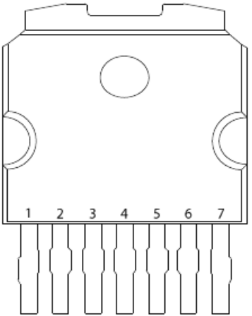
  • Package: PowerSO-10

Pin Configuration and Descriptions

Pin Number Name Description
1 OUT Output to load, connects to the low side of the load
2 GND Ground reference for the IC
3 IN Input control signal, typically from a microcontroller
4 Vcc Supply voltage for the IC
5 DIAG Diagnostic output, indicates fault conditions
6-10 TAB Exposed pad for enhanced thermal dissipation, must be connected to GND

Usage Instructions

How to Use the VN7003ALH in a Circuit

  1. Power Supply Connection: Connect the Vcc pin to a stable 5.5V to 36V power supply. Ensure that the power supply can handle the current requirements of the load.
  2. Load Connection: Connect the load to the OUT pin. The other side of the load should be connected to the positive supply voltage.
  3. Input Signal: The IN pin should be connected to a digital output from a microcontroller. A logic high signal will turn on the driver, allowing current to flow through the load.
  4. Grounding: Connect the GND pin and the TAB (pins 6-10) to the system ground.
  5. Diagnostic Feature: The DIAG pin can be connected to a microcontroller input to monitor the status of the driver and the load.

Important Considerations and Best Practices

  • Decoupling Capacitors: Place a decoupling capacitor close to the Vcc pin to filter out voltage spikes and noise.
  • Heat Dissipation: Ensure proper heat sinking for the IC, especially when driving high current loads.
  • Input Signal: The input signal voltage level should be compatible with the logic level of the microcontroller.
  • Protection Diodes: When driving inductive loads, use a flyback diode to prevent voltage spikes during turn-off.

Troubleshooting and FAQs

Common Issues

  • Driver Does Not Turn On: Check the input signal and power supply connections. Ensure the supply voltage is within the specified range.
  • Overheating: Verify that the current through the load does not exceed the continuous current rating. Improve heat sinking if necessary.
  • Diagnostic Flag Active: If the DIAG pin indicates a fault, check for overvoltage, overtemperature, or wiring issues.

Solutions and Tips for Troubleshooting

  • Check Connections: Ensure all pins are properly soldered and connected.
  • Monitor Supply Voltage: Use a multimeter to verify that the supply voltage is stable and within the specified range.
  • Inspect Load: Confirm that the load does not have a short circuit or other issues causing excessive current draw.

FAQs

Q: Can the VN7003ALH be used with PWM signals? A: Yes, the VN7003ALH can be used with PWM signals to control the power delivered to the load.

Q: What is the maximum frequency for the PWM signal? A: The maximum frequency for the PWM signal will depend on the application and thermal considerations. Consult the datasheet for detailed information.

Q: How do I know if the IC is in a fault condition? A: The DIAG pin will provide a fault indication. Connecting this pin to a microcontroller can help identify and diagnose the specific fault condition.

Example Code for Arduino UNO

// Define the VN7003ALH control and diagnostic pins
const int controlPin = 3; // IN pin connected to digital pin 3
const int diagPin = 2;    // DIAG pin connected to digital pin 2

void setup() {
  pinMode(controlPin, OUTPUT);
  pinMode(diagPin, INPUT);
  Serial.begin(9600);
}

void loop() {
  // Turn on the VN7003ALH
  digitalWrite(controlPin, HIGH);
  delay(1000); // Wait for 1 second

  // Turn off the VN7003ALH
  digitalWrite(controlPin, LOW);
  delay(1000); // Wait for 1 second

  // Read the diagnostic pin
  int diagState = digitalRead(diagPin);
  if (diagState == HIGH) {
    // Fault condition detected, handle accordingly
    Serial.println("Fault detected!");
  }
}

This example demonstrates basic control of the VN7003ALH using an Arduino UNO. The control pin is toggled to switch the driver on and off, while the diagnostic pin is monitored for fault conditions.