How to Use 12V solenoid lock: Examples, Pinouts, and Specs
Introduction
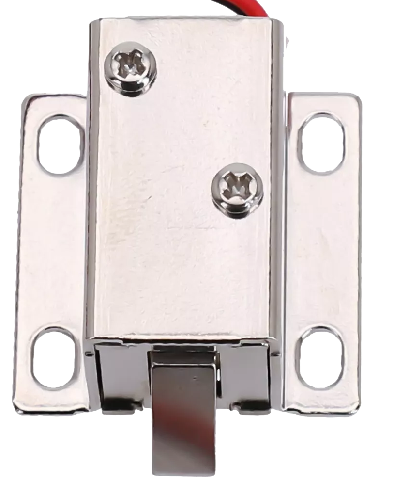
The 12V solenoid lock is an electromechanical device designed to provide secure access control. It operates by using a solenoid to control the locking mechanism, which is activated when a 12V DC power supply is applied. This component is widely used in applications such as electronic door locks, vending machines, lockers, and other automated security systems. Its compact design and reliable operation make it a popular choice for projects requiring controlled access.
Explore Projects Built with 12V solenoid lock
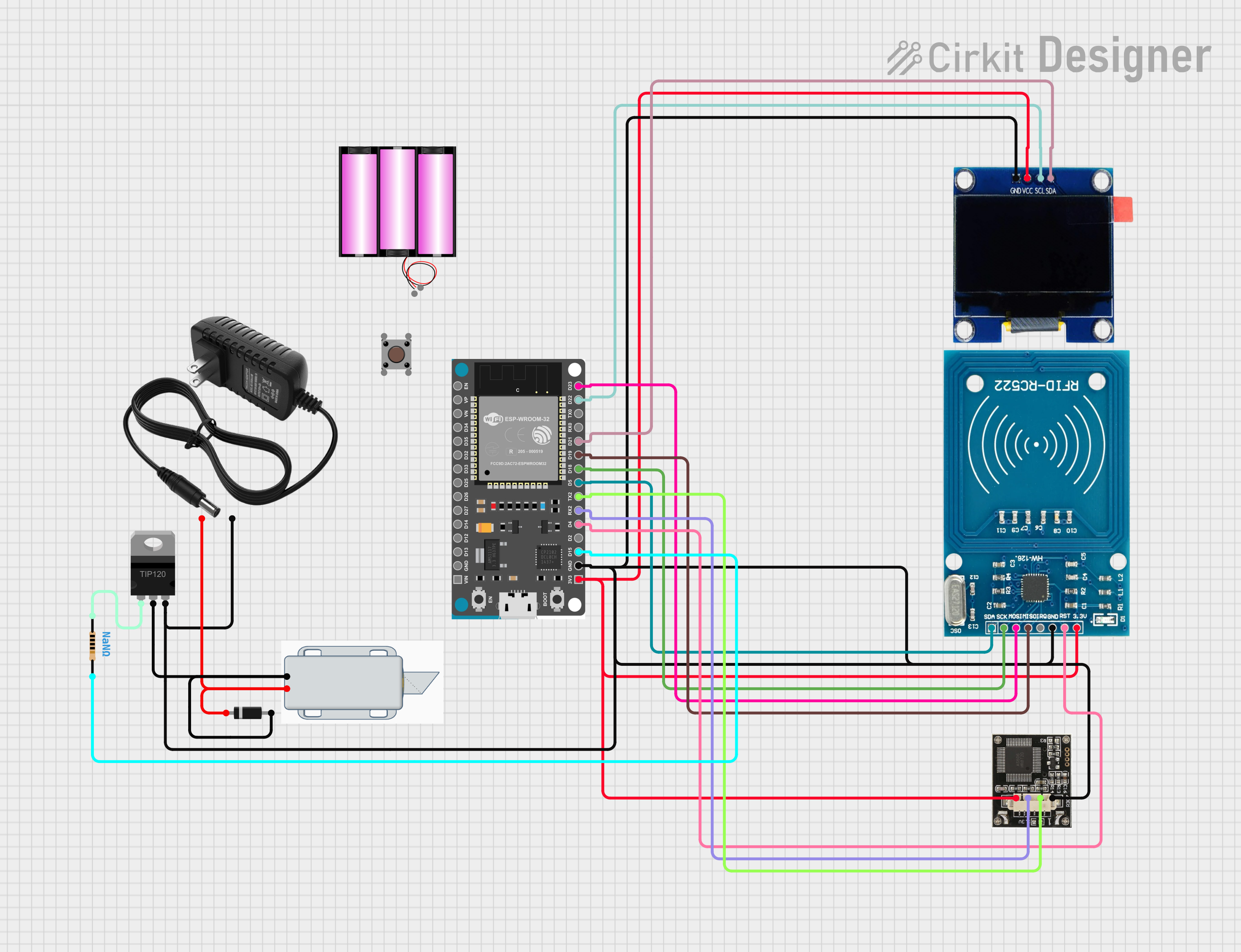
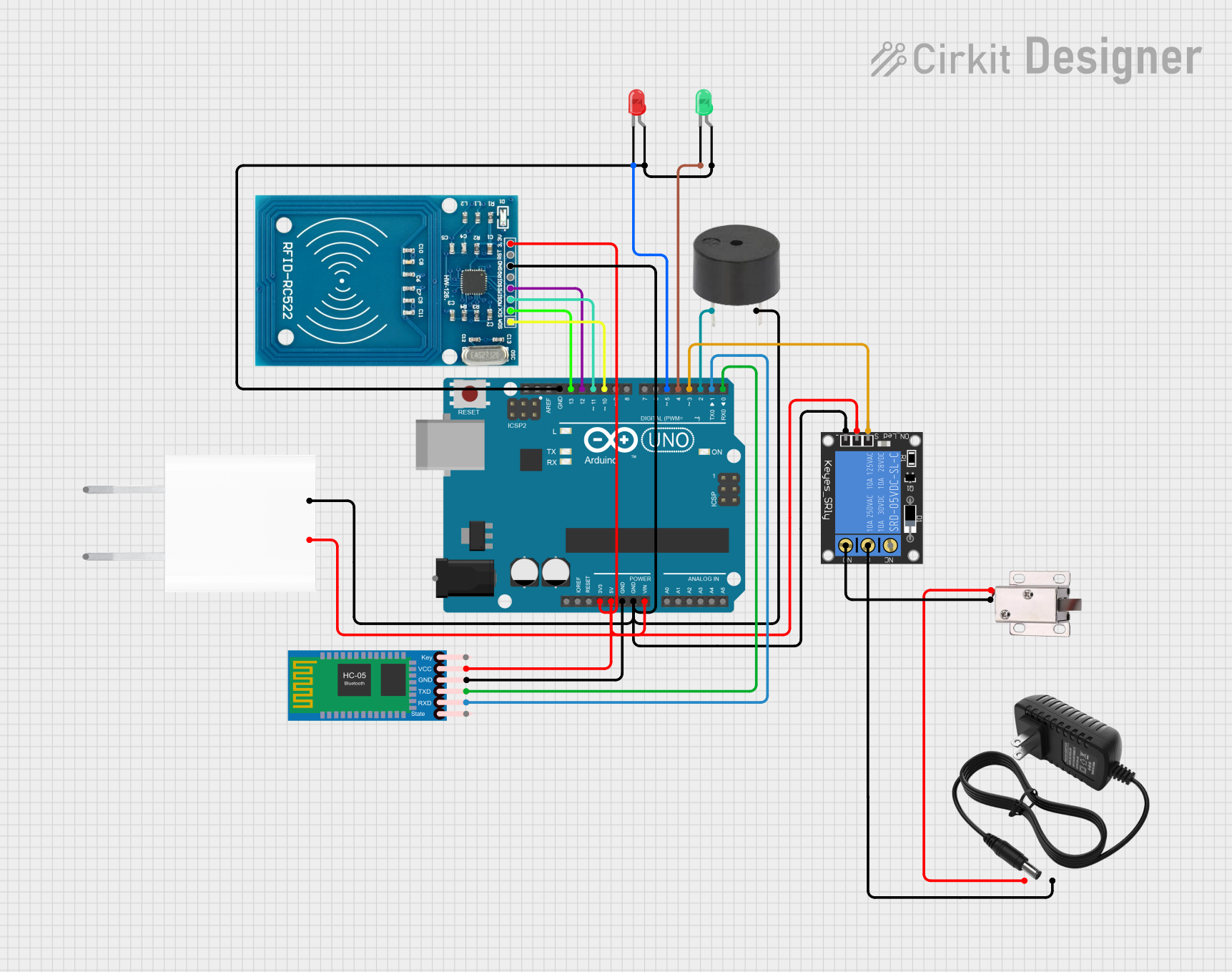
Explore Projects Built with 12V solenoid lock
Technical Specifications
- Operating Voltage: 12V DC
- Current Consumption: 0.5A to 1A (depending on load and duration)
- Power Consumption: Approximately 6W to 12W
- Actuation Type: Pull-type solenoid
- Material: Metal housing with a durable locking mechanism
- Dimensions: Typically 55mm x 40mm x 27mm (may vary by model)
- Weight: ~150g
- Operating Temperature: -10°C to 50°C
- Cable Length: ~15cm (may vary by model)
Pin Configuration and Descriptions
The 12V solenoid lock typically has two wires for connection:
| Wire Color | Description |
|---|---|
| Red | Positive terminal (+12V DC) |
| Black | Negative terminal (Ground) |
Usage Instructions
How to Use the Component in a Circuit
- Power Supply: Connect the red wire to the positive terminal of a 12V DC power supply and the black wire to the ground terminal. Ensure the power supply can provide sufficient current (at least 1A).
- Control Mechanism: Use a relay module, transistor, or MOSFET to control the solenoid lock from a microcontroller (e.g., Arduino). Directly connecting the solenoid to a microcontroller is not recommended due to high current requirements.
- Diode Protection: Place a flyback diode (e.g., 1N4007) across the solenoid terminals to protect the circuit from voltage spikes caused by the solenoid's inductive load.
Important Considerations and Best Practices
- Power Supply: Ensure the power supply is stable and capable of delivering the required current.
- Heat Management: Avoid prolonged activation of the solenoid to prevent overheating.
- Mounting: Securely mount the solenoid lock to prevent mechanical stress on the wires or housing.
- Polarity: Always connect the wires with the correct polarity to avoid damage.
Example: Connecting to an Arduino UNO
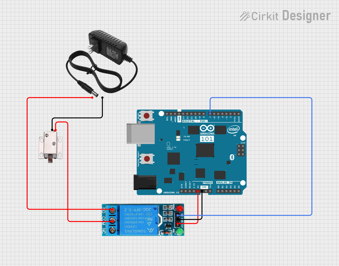
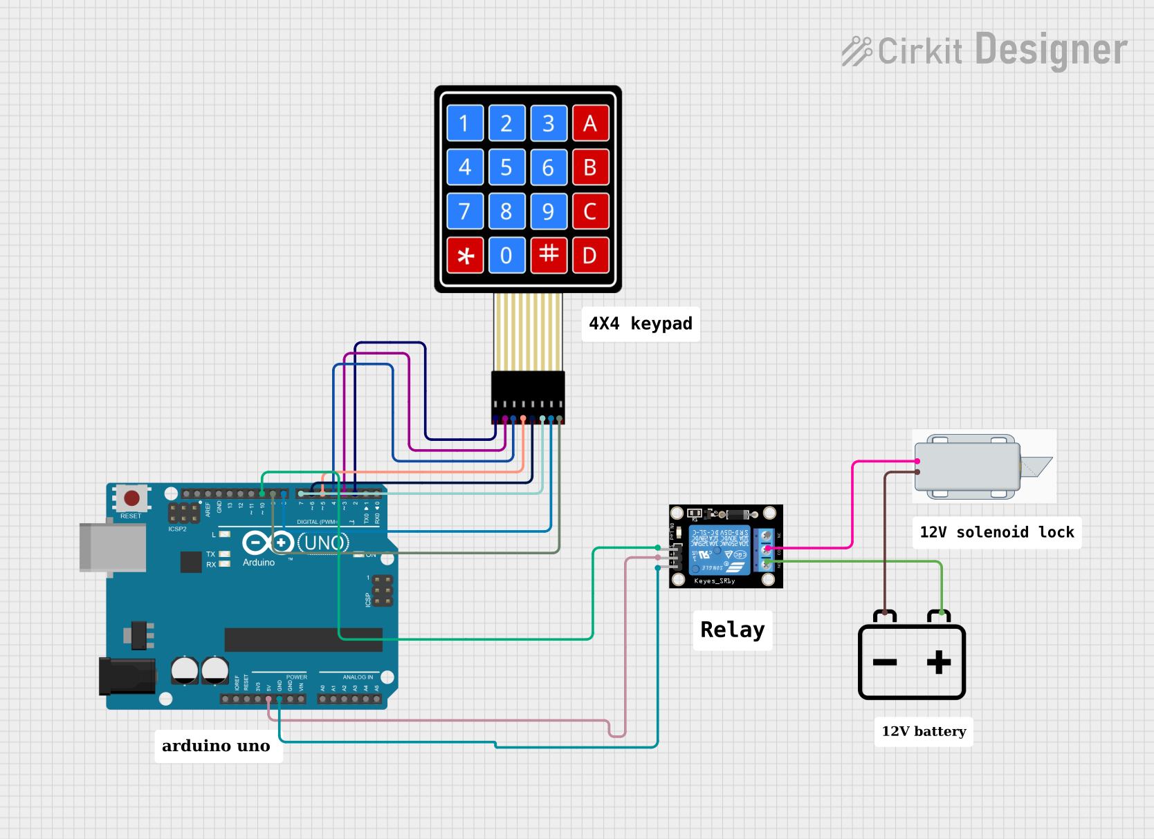
Below is an example of how to control a 12V solenoid lock using an Arduino UNO and a relay module.
Circuit Diagram
- Connect the solenoid lock to the relay module's NO (Normally Open) and COM (Common) terminals.
- Connect the relay module's VCC, GND, and IN pins to the Arduino's 5V, GND, and a digital pin (e.g., D7), respectively.
- Use an external 12V power supply to power the solenoid lock.
Arduino Code
// Example code to control a 12V solenoid lock using Arduino UNO
// The solenoid lock is connected to a relay module controlled by pin D7.

const int relayPin = 7; // Define the pin connected to the relay module

void setup() {
  pinMode(relayPin, OUTPUT); // Set the relay pin as an output
  digitalWrite(relayPin, LOW); // Ensure the relay is off initially
}

void loop() {
  // Activate the solenoid lock
  digitalWrite(relayPin, HIGH); // Turn on the relay
  delay(5000); // Keep the lock activated for 5 seconds

  // Deactivate the solenoid lock
  digitalWrite(relayPin, LOW); // Turn off the relay
  delay(5000); // Wait for 5 seconds before reactivating
}
Troubleshooting and FAQs
Common Issues
The solenoid lock does not activate:
- Check the power supply voltage and current. Ensure it is 12V DC and can provide at least 1A.
- Verify the wiring connections, especially the polarity of the wires.
- Ensure the relay or control circuit is functioning correctly.
The solenoid lock gets hot:
- Avoid keeping the solenoid activated for extended periods.
- Check for any obstructions in the locking mechanism that may cause excessive current draw.
The Arduino resets when activating the solenoid:
- This may be caused by voltage spikes or insufficient power supply. Add a flyback diode across the solenoid terminals and ensure the Arduino has a separate power source.
Tips for Troubleshooting
- Use a multimeter to measure the voltage and current at the solenoid terminals.
- Test the solenoid lock with a direct 12V DC power supply to confirm its functionality.
- If using a relay module, ensure the relay's input signal is correctly driven by the microcontroller.
By following this documentation, you can effectively integrate and troubleshoot a 12V solenoid lock in your projects.