How to Use K230 Vision Module: Examples, Pinouts, and Specs
Introduction
The K230 Vision Module by Yahboom is an advanced imaging sensor designed for robotics and automation applications. It combines high-resolution image capture with real-time processing capabilities, making it ideal for tasks such as object detection, tracking, and navigation. The module is compact, efficient, and easy to integrate with microcontrollers, including popular platforms like Arduino and Raspberry Pi.
Explore Projects Built with K230 Vision Module


Explore Projects Built with K230 Vision Module
Common Applications
- Object detection and recognition in robotics
- Autonomous navigation for drones and vehicles
- Industrial automation and quality control
- Gesture recognition and human-machine interaction
- Surveillance and security systems
Technical Specifications
The K230 Vision Module is built to deliver high performance in demanding environments. Below are its key technical details:
General Specifications
| Parameter | Value |
|---|---|
| Manufacturer | Yahboom |
| Part ID | K230 |
| Image Sensor Type | CMOS |
| Resolution | 1920 x 1080 (Full HD) |
| Frame Rate | Up to 60 FPS |
| Processing Unit | Integrated AI co-processor |
| Communication Interfaces | UART, I2C, SPI, USB |
| Operating Voltage | 5V DC |
| Power Consumption | 2W (typical) |
| Dimensions | 40mm x 40mm x 15mm |
| Weight | 25g |
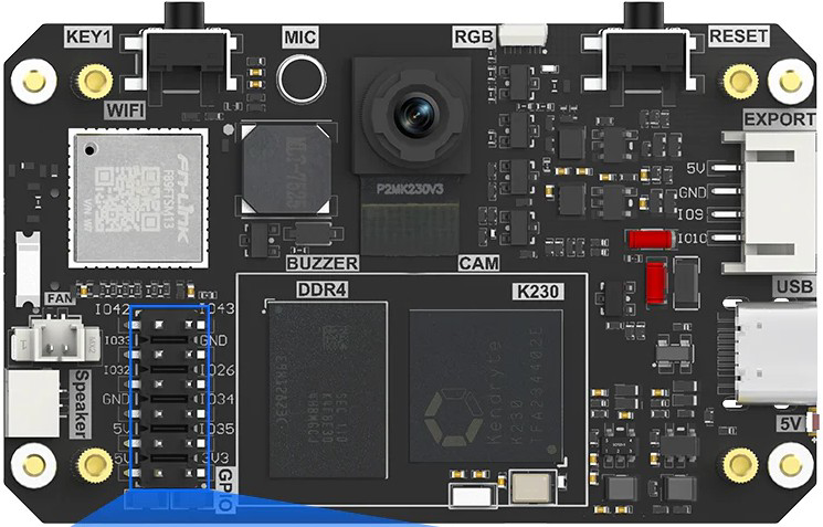
Pin Configuration
The K230 Vision Module features a 10-pin interface for easy integration. Below is the pinout and description:
| Pin Number | Pin Name | Description |
|---|---|---|
| 1 | VCC | Power supply input (5V DC) |
| 2 | GND | Ground |
| 3 | TX | UART Transmit |
| 4 | RX | UART Receive |
| 5 | SCL | I2C Clock |
| 6 | SDA | I2C Data |
| 7 | CS | SPI Chip Select |
| 8 | MOSI | SPI Master Out Slave In |
| 9 | MISO | SPI Master In Slave Out |
| 10 | SCK | SPI Clock |
Usage Instructions
The K230 Vision Module is designed for straightforward integration into various systems. Follow the steps below to use the module effectively:
Connecting the Module
- Power Supply: Connect the VCC pin to a 5V DC power source and the GND pin to ground.
- Communication Interface: Choose a communication protocol (UART, I2C, or SPI) based on your application:
- For UART, connect the TX and RX pins to the corresponding pins on your microcontroller.
- For I2C, connect the SCL and SDA pins to the I2C bus of your microcontroller.
- For SPI, connect CS, MOSI, MISO, and SCK to the respective SPI pins on your microcontroller.
- Optional USB Connection: Use the USB interface for direct connection to a PC for testing or firmware updates.
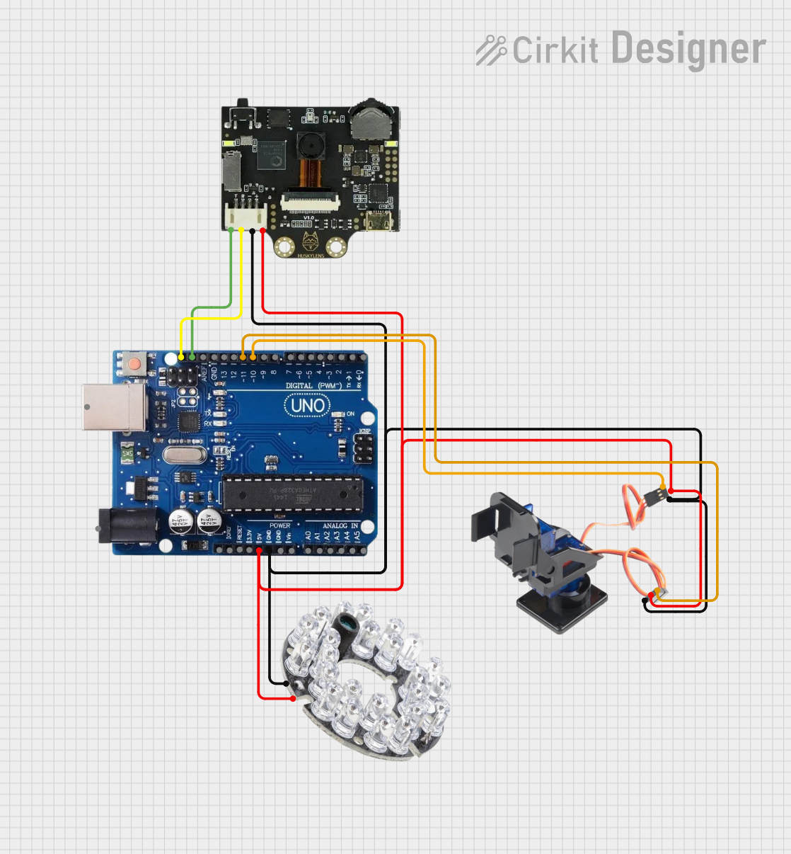
Example: Using with Arduino UNO
The following example demonstrates how to interface the K230 Vision Module with an Arduino UNO using UART communication.
Wiring Diagram
| K230 Pin | Arduino Pin |
|---|---|
| VCC | 5V |
| GND | GND |
| TX | RX (Pin 0) |
| RX | TX (Pin 1) |
Arduino Code
// Include necessary libraries
#include <SoftwareSerial.h>

// Define RX and TX pins for SoftwareSerial
SoftwareSerial K230Serial(10, 11); // RX = Pin 10, TX = Pin 11

void setup() {
  // Initialize serial communication with the K230 Vision Module
  K230Serial.begin(115200); // Set baud rate to 115200
  Serial.begin(9600);       // For debugging via Serial Monitor

  // Notify user that setup is complete
  Serial.println("K230 Vision Module Initialized");
}

void loop() {
  // Check if data is available from the K230 Vision Module
  if (K230Serial.available()) {
    // Read data from the module
    String data = K230Serial.readString();

    // Print the received data to the Serial Monitor
    Serial.println("Data from K230: " + data);
  }

  // Optional: Send commands to the K230 Vision Module
  if (Serial.available()) {
    String command = Serial.readString();
    K230Serial.println(command); // Send command to the module
  }
}
Best Practices
- Ensure the module is powered with a stable 5V DC supply to avoid damage.
- Use level shifters if interfacing with a 3.3V microcontroller.
- Avoid placing the module in direct sunlight or extremely dusty environments for optimal performance.
- Regularly update the firmware to access the latest features and improvements.
Troubleshooting and FAQs
Common Issues and Solutions
No Data Received from the Module
- Cause: Incorrect baud rate or wiring.
- Solution: Verify the baud rate (default is 115200) and check the connections.
Module Not Powering On
- Cause: Insufficient power supply.
- Solution: Ensure the power source provides a stable 5V DC with at least 500mA current.
Unstable or Noisy Data
- Cause: Electrical interference or poor grounding.
- Solution: Use shorter wires and ensure proper grounding.
Firmware Update Fails
- Cause: Interrupted connection during the update process.
- Solution: Reconnect the module and restart the update process.
FAQs
Q1: Can the K230 Vision Module detect multiple objects simultaneously?
A1: Yes, the module supports multi-object detection and tracking, depending on the processing algorithm used.
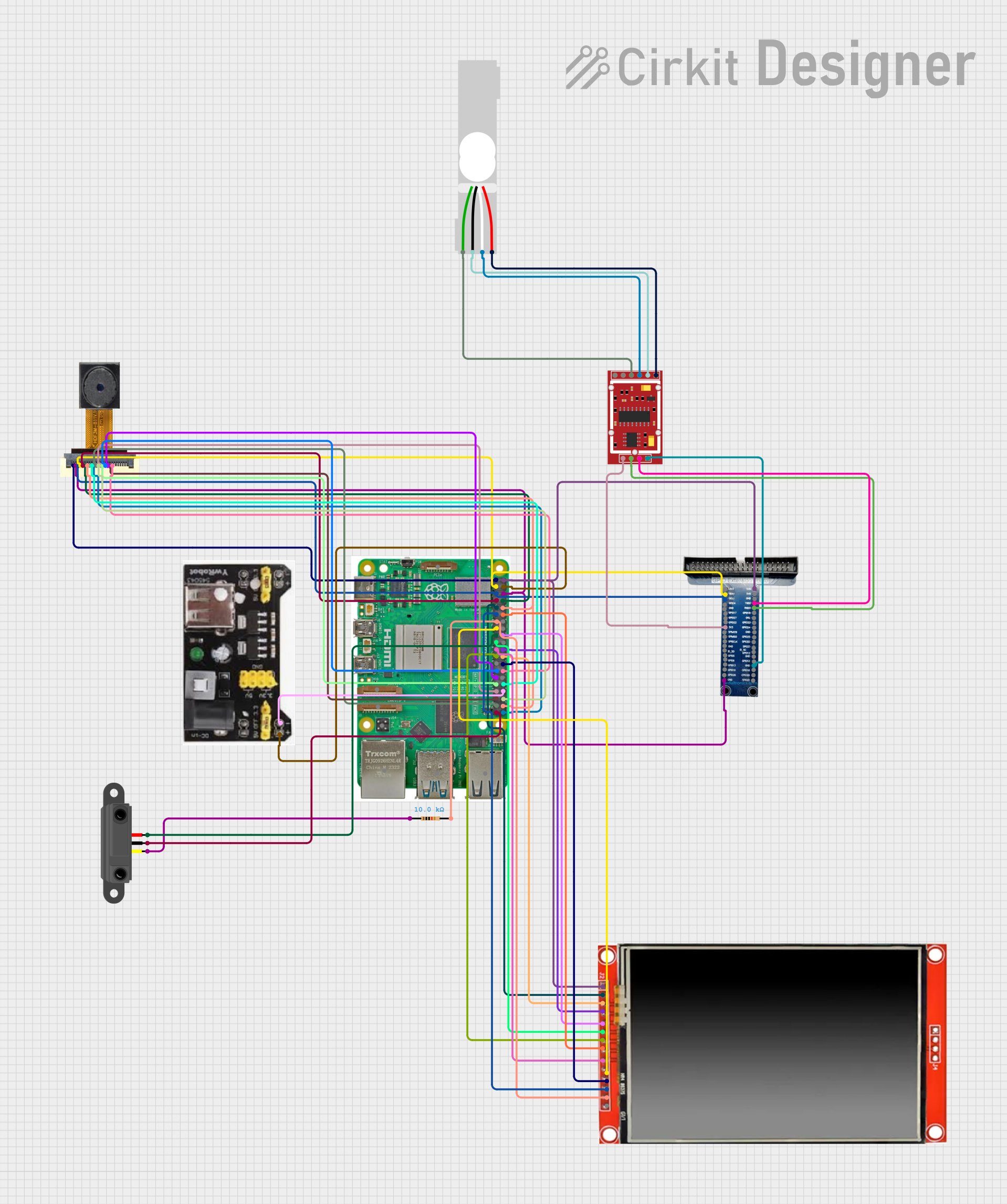
Q2: Is the module compatible with Raspberry Pi?
A2: Yes, the K230 Vision Module can be connected to Raspberry Pi via UART, I2C, or SPI.
Q3: What is the maximum cable length for communication?
A3: For UART and I2C, keep the cable length under 1 meter to avoid signal degradation. For SPI, shorter cables (less than 50cm) are recommended.
Q4: Can the module operate outdoors?
A4: The module can operate outdoors but should be protected from direct sunlight, rain, and extreme temperatures.
By following this documentation, you can effectively integrate and utilize the Yahboom K230 Vision Module in your projects.