Cirkit Designer Logo
Cirkit Designer
Your all-in-one circuit design IDE
Home / 
Component Documentation

How to Use SparkFun Qwiic GPS-RTK2 - ublox ZED-F9P: Examples, Pinouts, and Specs

Image of SparkFun Qwiic GPS-RTK2 - ublox ZED-F9P
Cirkit Designer LogoDesign with SparkFun Qwiic GPS-RTK2 - ublox ZED-F9P in Cirkit Designer

Introduction

The SparkFun Qwiic GPS-RTK2 is a cutting-edge Global Navigation Satellite System (GNSS) module that offers high-precision, dual-band RTK capabilities. It is built around the ublox ZED-F9P chipset, which is renowned for its accurate positioning and timing solutions. This module is designed for applications requiring centimeter-level accuracy such as autonomous vehicles, drones, precision agriculture, and surveying.

Explore Projects Built with SparkFun Qwiic GPS-RTK2 - ublox ZED-F9P

Use Cirkit Designer to design, explore, and prototype these projects online. Some projects support real-time simulation. Click "Open Project" to start designing instantly!
ESP8266 and GPS-RTK2 Based Real-Time GPS Tracker with Bluetooth and APC220 Communication
Image of PANDURTKU0001_1: A project utilizing SparkFun Qwiic GPS-RTK2 - ublox ZED-F9P in a practical application
This circuit integrates a GPS module, an ESP8266 microcontroller, a Bluetooth module, and an APC220 RF module to collect and transmit GPS data. The ESP8266 reads GPS data from the SparkFun Qwiic GPS-RTK2 module and can communicate this data via Bluetooth and RF transmission. The system is powered by a 5V battery and includes an embedded GPS antenna for signal reception.
Cirkit Designer LogoOpen Project in Cirkit Designer
Battery-Powered GPS Tracker with Bluetooth and APC220 Communication
Image of PANDURTKU0001_basic: A project utilizing SparkFun Qwiic GPS-RTK2 - ublox ZED-F9P in a practical application
This circuit integrates a SparkFun Qwiic GPS-RTK2 module with an APC220 radio module and an HC-05 Bluetooth module to provide GPS data transmission via both radio and Bluetooth. The circuit is powered by a 5V battery and includes switches to control power to the GPS module and the APC220 module, with an embedded GPS antenna for signal reception.
Cirkit Designer LogoOpen Project in Cirkit Designer
ESP32-Based GPS Tracker with OLED Display and Firebase Integration
Image of ecs: A project utilizing SparkFun Qwiic GPS-RTK2 - ublox ZED-F9P in a practical application
This circuit is a GPS tracking system that uses an ESP32 microcontroller to read location data from a NEO-6M GPS module and display information on a 0.96" OLED screen. The system is powered by a 2000mAh battery with a lithium-ion charger, and it uploads the GPS data to Firebase via WiFi. Additional components include an MPU6050 accelerometer/gyroscope for motion sensing and a buzzer for alerts.
Cirkit Designer LogoOpen Project in Cirkit Designer
Arduino UNO with A9G GSM/GPRS and Dual VL53L1X Distance Sensors
Image of TED CIRCUIT : A project utilizing SparkFun Qwiic GPS-RTK2 - ublox ZED-F9P in a practical application
This circuit features an Arduino UNO microcontroller interfaced with an A9G GSM/GPRS+GPS/BDS module and two VL53L1X time-of-flight distance sensors. The A9G module is connected to the Arduino via serial communication for GPS and GSM functionalities, while both VL53L1X sensors are connected through I2C with shared SDA and SCL lines and individual SHUT pins for selective sensor activation. The Arduino is programmed to control these peripherals, although the specific functionality is not detailed in the provided code.
Cirkit Designer LogoOpen Project in Cirkit Designer

Explore Projects Built with SparkFun Qwiic GPS-RTK2 - ublox ZED-F9P

Use Cirkit Designer to design, explore, and prototype these projects online. Some projects support real-time simulation. Click "Open Project" to start designing instantly!
Image of PANDURTKU0001_1: A project utilizing SparkFun Qwiic GPS-RTK2 - ublox ZED-F9P in a practical application
ESP8266 and GPS-RTK2 Based Real-Time GPS Tracker with Bluetooth and APC220 Communication
This circuit integrates a GPS module, an ESP8266 microcontroller, a Bluetooth module, and an APC220 RF module to collect and transmit GPS data. The ESP8266 reads GPS data from the SparkFun Qwiic GPS-RTK2 module and can communicate this data via Bluetooth and RF transmission. The system is powered by a 5V battery and includes an embedded GPS antenna for signal reception.
Cirkit Designer LogoOpen Project in Cirkit Designer
Image of PANDURTKU0001_basic: A project utilizing SparkFun Qwiic GPS-RTK2 - ublox ZED-F9P in a practical application
Battery-Powered GPS Tracker with Bluetooth and APC220 Communication
This circuit integrates a SparkFun Qwiic GPS-RTK2 module with an APC220 radio module and an HC-05 Bluetooth module to provide GPS data transmission via both radio and Bluetooth. The circuit is powered by a 5V battery and includes switches to control power to the GPS module and the APC220 module, with an embedded GPS antenna for signal reception.
Cirkit Designer LogoOpen Project in Cirkit Designer
Image of ecs: A project utilizing SparkFun Qwiic GPS-RTK2 - ublox ZED-F9P in a practical application
ESP32-Based GPS Tracker with OLED Display and Firebase Integration
This circuit is a GPS tracking system that uses an ESP32 microcontroller to read location data from a NEO-6M GPS module and display information on a 0.96" OLED screen. The system is powered by a 2000mAh battery with a lithium-ion charger, and it uploads the GPS data to Firebase via WiFi. Additional components include an MPU6050 accelerometer/gyroscope for motion sensing and a buzzer for alerts.
Cirkit Designer LogoOpen Project in Cirkit Designer
Image of TED CIRCUIT : A project utilizing SparkFun Qwiic GPS-RTK2 - ublox ZED-F9P in a practical application
Arduino UNO with A9G GSM/GPRS and Dual VL53L1X Distance Sensors
This circuit features an Arduino UNO microcontroller interfaced with an A9G GSM/GPRS+GPS/BDS module and two VL53L1X time-of-flight distance sensors. The A9G module is connected to the Arduino via serial communication for GPS and GSM functionalities, while both VL53L1X sensors are connected through I2C with shared SDA and SCL lines and individual SHUT pins for selective sensor activation. The Arduino is programmed to control these peripherals, although the specific functionality is not detailed in the provided code.
Cirkit Designer LogoOpen Project in Cirkit Designer

Common Applications and Use Cases

  • Autonomous navigation for drones and ground vehicles
  • Precision agriculture for accurate field mapping and machinery guidance
  • Surveying and mapping for construction and land management
  • Time synchronization for critical infrastructure

Technical Specifications

Key Technical Details

  • Receiver Type: 184-channel u-blox F9 engine, GNSS quad-band receiver
  • Position Accuracy: Down to 1 cm with RTK
  • Update Rate: Up to 20 Hz
  • Operating Temperature: -40°C to 85°C
  • Communication Interface: UART, SPI, I2C (Qwiic)
  • Input Voltage: 3.3V to 5.5V
  • Power Consumption: 68mA to 130mA

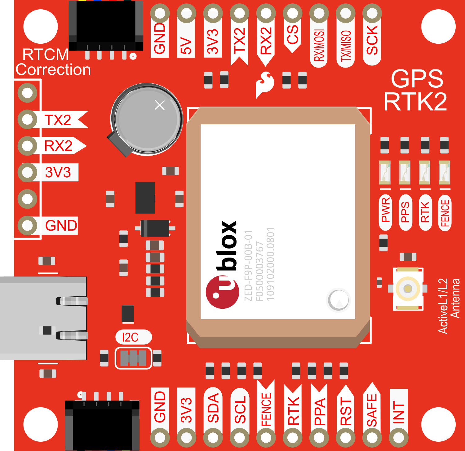
Pin Configuration and Descriptions

Pin Number Name Description
1 GND Ground connection
2 3.3V Power supply input (3.3V)
3 SDA I2C data line for Qwiic connector
4 SCL I2C clock line for Qwiic connector
5 RX UART receive pin
6 TX UART transmit pin
7 INT Interrupt pin
8 RST Reset pin

Usage Instructions

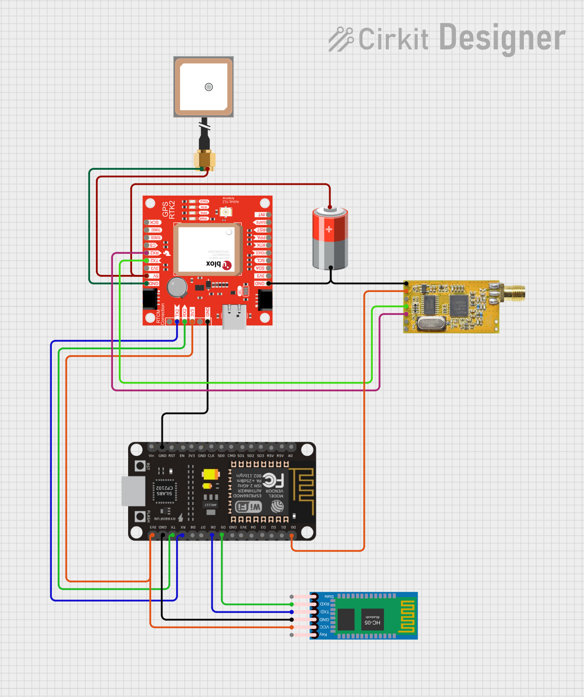
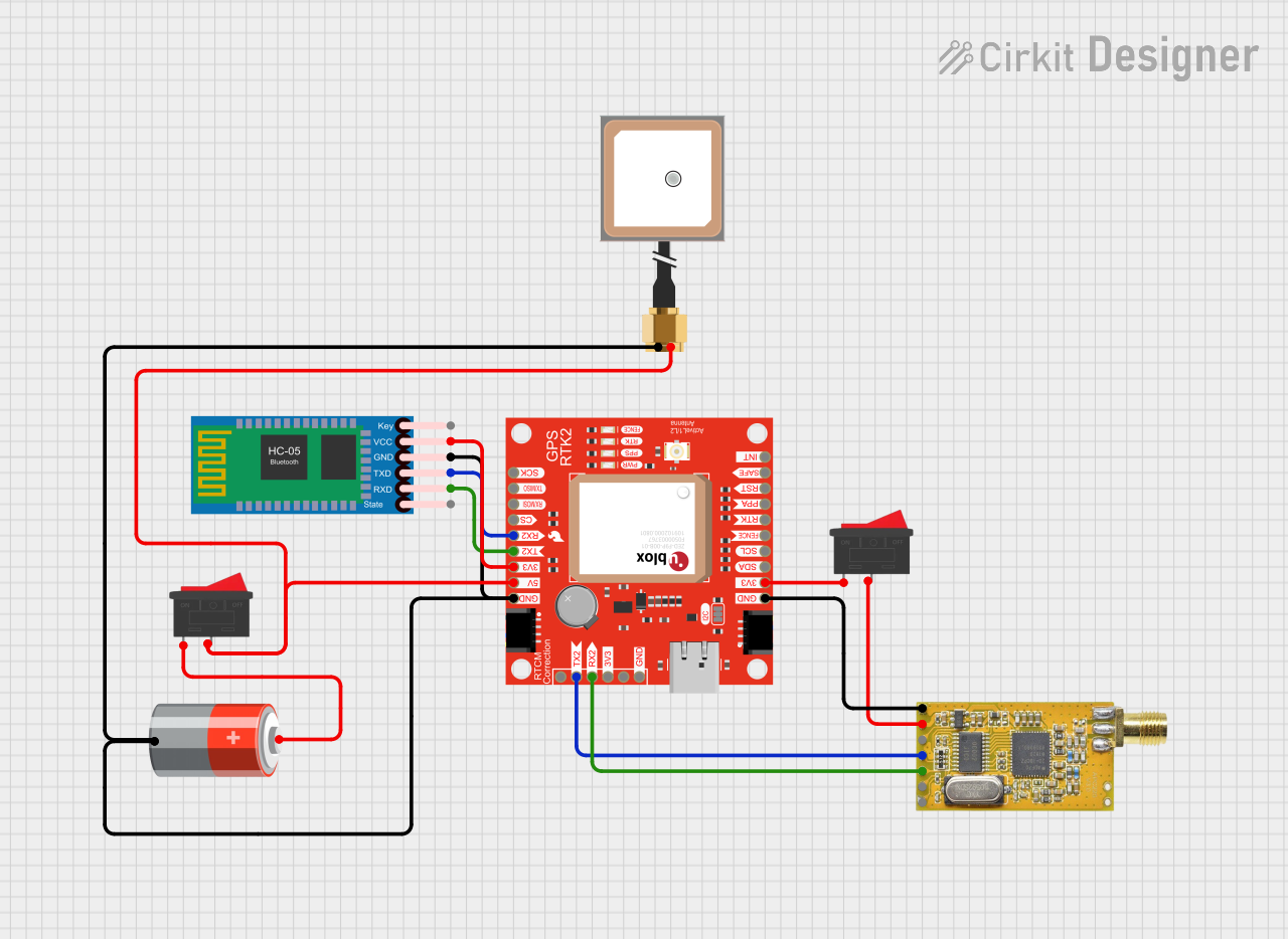
How to Use the Component in a Circuit

  1. Powering the Module: Connect the 3.3V and GND pins to a stable power supply within the specified voltage range.
  2. Data Communication: Choose the communication interface (UART, SPI, or I2C) that best fits your application. For I2C, use the Qwiic connector for easy interfacing.
  3. Antenna Connection: Attach a GNSS antenna to the module to receive satellite signals.
  4. Configuration: Use the u-center software from u-blox to configure the module settings as per your requirements.

Important Considerations and Best Practices

  • Ensure that the antenna has a clear view of the sky for optimal satellite signal reception.
  • Avoid placing the module near sources of electromagnetic interference.
  • Use proper ESD precautions when handling the module to prevent damage.
  • For battery-powered applications, consider the power consumption and optimize the update rate accordingly.

Example Code for Arduino UNO

#include <Wire.h>
#include <SparkFun_u-blox_GNSS_Arduino_Library.h>

SFE_UBLOX_GNSS myGNSS;

void setup() {
  Wire.begin();
  Serial.begin(115200);
  while (!Serial); // Wait for serial port to connect

  if (myGNSS.begin() == false) {
    Serial.println(F("u-blox GNSS not detected at default I2C address. Please check wiring."));
    while (1);
  }
}

void loop() {
  if (myGNSS.getGnssFixOk()) {
    double latitude = myGNSS.getLatitude();
    double longitude = myGNSS.getLongitude();
    double altitude = myGNSS.getAltitude();

    Serial.print(F("Latitude: "));
    Serial.print(latitude, 8);
    Serial.print(F(" Longitude: "));
    Serial.print(longitude, 8);
    Serial.print(F(" Altitude: "));
    Serial.print(altitude);
    Serial.println(F("m"));
  }
  delay(1000);
}

This example initializes the GNSS module and prints the latitude, longitude, and altitude to the serial monitor once a second.

Troubleshooting and FAQs

Common Issues

  • No Fix: Ensure the antenna is properly connected and has a clear view of the sky.
  • Inaccurate Readings: Check that the module is configured for the correct GNSS constellations and modes.
  • Communication Failure: Verify that the wiring matches the chosen communication protocol and that there are no loose connections.

Solutions and Tips for Troubleshooting

  • Power Cycle: If the module is unresponsive, try power cycling it.
  • Factory Reset: Perform a factory reset using the u-center software if configuration issues persist.
  • Firmware Update: Ensure the module's firmware is up to date for optimal performance.

FAQs

Q: Can the module be used without an external antenna? A: No, an external GNSS antenna is required for the module to function correctly.

Q: What is the maximum update rate? A: The module can provide position updates at up to 20 Hz, depending on the configuration.

Q: Is the module compatible with all GNSS constellations? A: Yes, the ZED-F9P supports multiple constellations including GPS, GLONASS, Galileo, and BeiDou.

Q: How do I connect the module to my microcontroller? A: You can connect via UART, SPI, or I2C. For Arduino boards, I2C with the Qwiic system is the simplest method.

For further assistance, please refer to the SparkFun Qwiic GPS-RTK2 datasheet and the u-blox ZED-F9P integration manual.