How to Use BLDC controller with Hall: Examples, Pinouts, and Specs
Introduction
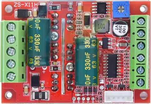
A Brushless DC (BLDC) controller with Hall effect sensors is an electronic device designed to regulate the operation of a brushless motor. Unlike traditional DC motors, BLDC motors do not use brushes for commutation. Instead, the controller relies on Hall effect sensors to detect the rotor's position, enabling precise control of the motor's speed, direction, and torque.
This type of controller is widely used in applications requiring high efficiency, reliability, and smooth operation. Common use cases include:
- Electric vehicles (e.g., e-bikes, scooters, and cars)
- Robotics and automation systems
- Drones and unmanned aerial vehicles (UAVs)
- Industrial machinery and conveyor systems
- HVAC systems (e.g., fans and compressors)
Explore Projects Built with BLDC controller with Hall
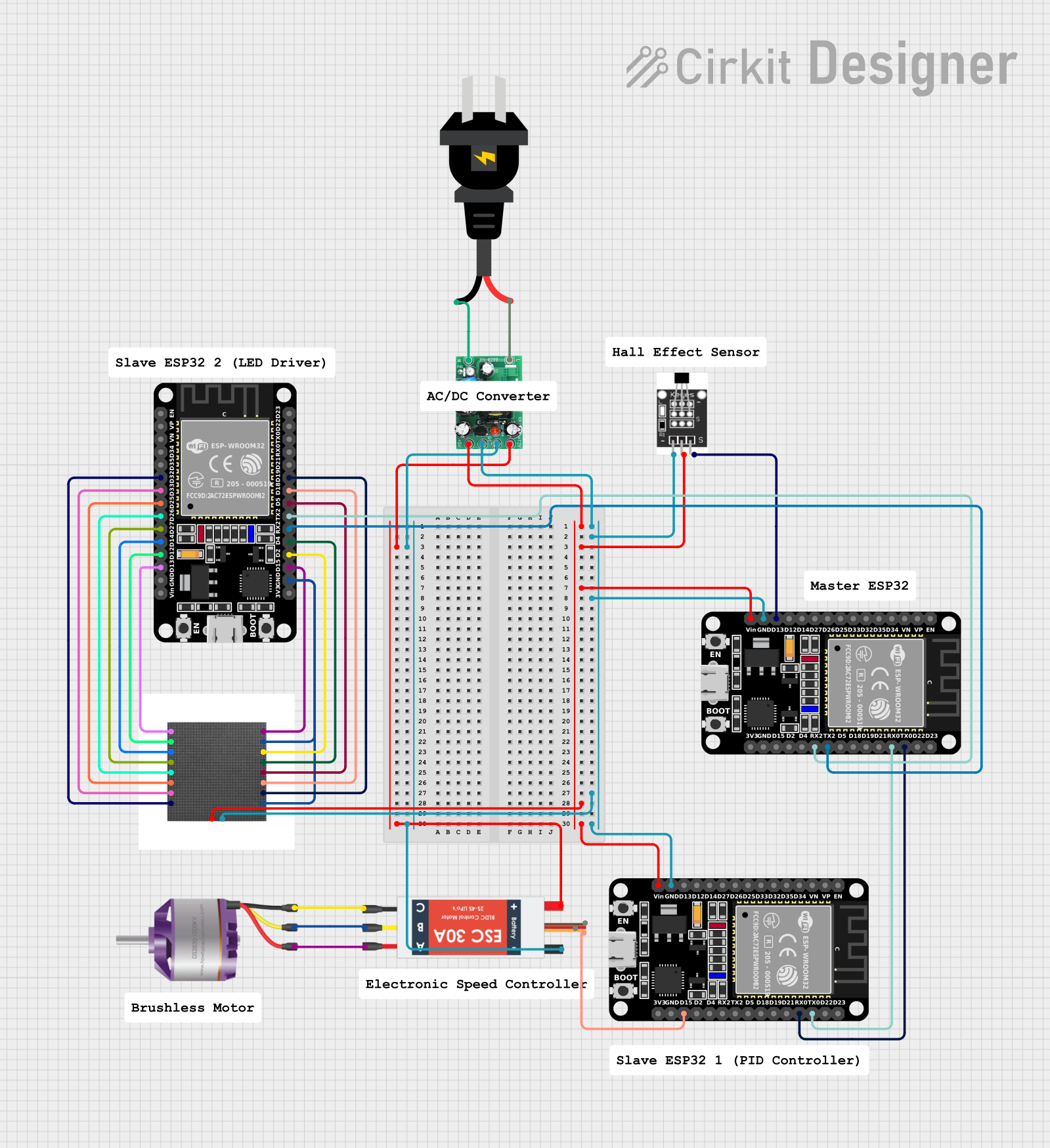


Explore Projects Built with BLDC controller with Hall
Technical Specifications
Key Technical Details
- Input Voltage Range: 12V to 48V DC (varies by model)
- Maximum Current: 10A to 50A (depending on the controller)
- Motor Compatibility: 3-phase BLDC motors with Hall sensors
- Control Modes: Speed control, torque control, and direction control
- Signal Input: PWM, analog voltage, or UART (depending on the model)
- Hall Sensor Input Voltage: 5V DC
- Operating Temperature: -20°C to 85°C
- Protection Features: Overcurrent, overvoltage, undervoltage, and thermal protection
Pin Configuration and Descriptions
The pin configuration may vary slightly depending on the specific model of the BLDC controller. Below is a typical pinout for a BLDC controller with Hall sensors:
| Pin Name | Description |
|---|---|
| VCC | Positive power supply input (e.g., 12V to 48V DC). |
| GND | Ground connection for the power supply. |
| U, V, W | Outputs to the three motor phases (U, V, W). |
| H1, H2, H3 | Inputs from the Hall effect sensors (used for rotor position detection). |
| 5V | 5V output to power the Hall sensors. |
| PWM | Pulse Width Modulation input for speed control. |
| DIR | Direction control input (e.g., HIGH for forward, LOW for reverse). |
| BRAKE | Brake control input (e.g., HIGH to activate braking). |
| ENABLE | Enable input (e.g., HIGH to enable the controller, LOW to disable it). |
| UART_TX, UART_RX | UART communication pins for advanced control and monitoring (if supported). |
Usage Instructions
How to Use the Component in a Circuit
- Power Supply: Connect the VCC and GND pins to a DC power source within the specified voltage range (e.g., 12V to 48V). Ensure the power supply can provide sufficient current for the motor.
- Motor Connection: Connect the U, V, and W pins to the corresponding phases of the BLDC motor.
- Hall Sensor Connection: Connect the Hall sensor outputs (H1, H2, H3) to the controller's Hall input pins. Also, connect the Hall sensor's power and ground pins to the controller's 5V and GND pins.
- Control Inputs:
- Use the PWM pin to control the motor speed. A higher duty cycle corresponds to a higher speed.
- Use the DIR pin to set the motor's direction (e.g., HIGH for forward, LOW for reverse).
- Optionally, connect the BRAKE pin to activate the braking function when needed.
- Enable the Controller: Set the ENABLE pin HIGH to activate the controller.
Important Considerations and Best Practices
- Power Supply: Ensure the power supply voltage and current ratings match the motor and controller requirements.
- Wiring: Use appropriately rated wires for power and motor connections to avoid overheating or voltage drops.
- Cooling: If the controller operates at high currents, consider adding a heatsink or active cooling to prevent overheating.
- Startup Sequence: Always power on the controller before applying control signals to avoid erratic behavior.
- Hall Sensor Alignment: Ensure the Hall sensors are correctly aligned with the motor's rotor for accurate position detection.
Example Code for Arduino UNO
Below is an example of how to control a BLDC motor with a Hall controller using an Arduino UNO. The code uses PWM for speed control and a digital pin for direction control.
// Define pin connections
const int pwmPin = 9;      // PWM pin for speed control
const int dirPin = 8;      // Direction control pin
const int enablePin = 7;   // Enable pin for the controller

void setup() {
  // Set pin modes
  pinMode(pwmPin, OUTPUT);
  pinMode(dirPin, OUTPUT);
  pinMode(enablePin, OUTPUT);

  // Initialize the controller
  digitalWrite(enablePin, HIGH); // Enable the controller
  digitalWrite(dirPin, LOW);     // Set initial direction to forward
}

void loop() {
  // Example: Gradually increase motor speed
  for (int speed = 0; speed <= 255; speed++) {
    analogWrite(pwmPin, speed); // Set PWM duty cycle (0-255)
    delay(20);                  // Small delay for smooth acceleration
  }

  delay(2000); // Run at full speed for 2 seconds

  // Example: Reverse direction
  digitalWrite(dirPin, HIGH); // Change direction to reverse
  delay(1000);                // Wait for direction change

  // Gradually decrease motor speed
  for (int speed = 255; speed >= 0; speed--) {
    analogWrite(pwmPin, speed); // Decrease PWM duty cycle
    delay(20);                  // Small delay for smooth deceleration
  }

  delay(2000); // Pause before restarting the loop
}
Troubleshooting and FAQs
Common Issues and Solutions
Motor Does Not Start:
- Check the power supply voltage and current ratings.
- Verify all connections, especially the Hall sensor wiring.
- Ensure the ENABLE pin is set HIGH.
Motor Runs Erratically:
- Check the alignment of the Hall sensors with the rotor.
- Verify the PWM signal is within the correct frequency range (typically 1kHz to 20kHz).
- Inspect the motor phases (U, V, W) for loose or incorrect connections.
Controller Overheats:
- Ensure the controller is not exceeding its current rating.
- Add a heatsink or active cooling if necessary.
No Response to Control Signals:
- Verify the control signal connections (PWM, DIR, ENABLE).
- Check the Arduino code for errors or incorrect pin assignments.
FAQs
Can I use this controller with a sensorless BLDC motor? No, this controller requires Hall sensors for proper operation.
What happens if I reverse the Hall sensor connections? Incorrect Hall sensor wiring can cause erratic motor behavior or prevent the motor from starting.
What is the recommended PWM frequency? Most BLDC controllers operate well with a PWM frequency between 1kHz and 20kHz. Check the datasheet for your specific controller.
Can I use this controller with a 24V motor on a 48V power supply? No, the motor and power supply voltage ratings must match to avoid damage.
By following this documentation, you can effectively use a BLDC controller with Hall sensors in your projects.