
How to Use Adafruit JTAG 2x10 to SWD 2x5: Examples, Pinouts, and Specs
 Design with Adafruit JTAG 2x10 to SWD 2x5 in Cirkit Designer
Introduction
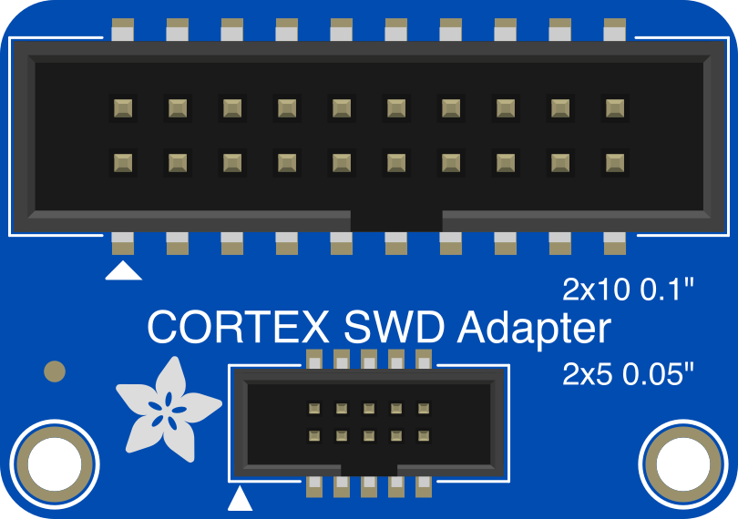
The Adafruit JTAG 2x10 to SWD 2x5 adapter (Part ID: 2094) is a compact and reliable connector adapter designed to convert a 2x10 JTAG interface to a 2x5 SWD (Serial Wire Debug) interface. This adapter is ideal for programming and debugging microcontrollers that utilize the SWD protocol. It simplifies the connection process by providing a seamless bridge between JTAG and SWD interfaces, making it an essential tool for embedded systems developers.
Explore Projects Built with Adafruit JTAG 2x10 to SWD 2x5
 Open Project in Cirkit Designer
 Open Project in Cirkit Designer
 Open Project in Cirkit Designer
 Open Project in Cirkit Designer
Explore Projects Built with Adafruit JTAG 2x10 to SWD 2x5
Open Project in Cirkit DesignerOpen Project in Cirkit DesignerOpen Project in Cirkit DesignerOpen Project in Cirkit DesignerCommon Applications and Use Cases
- Debugging and programming ARM Cortex-M microcontrollers using SWD.
- Converting legacy JTAG interfaces to the modern SWD standard.
- Prototyping and development of embedded systems.
- Use in conjunction with SWD-compatible debuggers such as ST-Link, J-Link, or CMSIS-DAP.
Technical Specifications
The Adafruit JTAG 2x10 to SWD 2x5 adapter is designed to meet the needs of developers working with modern microcontrollers. Below are the key technical details:
Key Specifications
- Manufacturer: Adafruit
- Part ID: 2094
- Input Interface: 2x10 JTAG (20-pin, 0.1" pitch)
- Output Interface: 2x5 SWD (10-pin, 0.05" pitch)
- Supported Protocols: SWD (Serial Wire Debug)
- Dimensions: 1.0" x 0.6" (approx.)
- Weight: ~2g
- Material: PCB with gold-plated connectors for durability and reliable signal transmission.
Pin Configuration and Descriptions
2x10 JTAG Input Pinout
| Pin Number | Signal Name | Description |
|---|---|---|
| 1 | VREF | Target reference voltage |
| 2 | GND | Ground |
| 3 | nTRST | Test reset (optional) |
| 4 | GND | Ground |
| 5 | TDI | Test Data In |
| 6 | GND | Ground |
| 7 | TMS | Test Mode Select |
| 8 | GND | Ground |
| 9 | TCK | Test Clock |
| 10 | GND | Ground |
| 11 | RTCK | Return Test Clock (optional) |
| 12 | GND | Ground |
| 13 | TDO | Test Data Out |
| 14 | GND | Ground |
| 15 | RESET | Target reset |
| 16 | GND | Ground |
| 17 | DBGRQ | Debug Request (optional) |
| 18 | GND | Ground |
| 19 | DBGACK | Debug Acknowledge (optional) |
| 20 | GND | Ground |
2x5 SWD Output Pinout
| Pin Number | Signal Name | Description |
|---|---|---|
| 1 | VREF | Target reference voltage |
| 2 | SWDIO | Serial Wire Debug I/O |
| 3 | GND | Ground |
| 4 | SWCLK | Serial Wire Clock |
| 5 | GND | Ground |
| 6 | NC | Not Connected |
| 7 | NC | Not Connected |
| 8 | NC | Not Connected |
| 9 | RESET | Target reset |
| 10 | GND | Ground |
Usage Instructions
How to Use the Adapter in a Circuit
- Connect the JTAG Interface: Plug the 2x10 JTAG connector into the JTAG header of your debugger or development board.
- Connect the SWD Interface: Attach the 2x5 SWD connector to the SWD header of your target microcontroller or development board.
- Verify Connections: Ensure that the VREF, SWDIO, SWCLK, and RESET lines are properly aligned and connected.
- Power the Target Board: Provide power to the target microcontroller board. The adapter does not supply power; it relies on the target board's power supply.
- Begin Debugging or Programming: Use your preferred debugging tool (e.g., OpenOCD, J-Link software, or STM32CubeProgrammer) to program or debug the target microcontroller.
Important Considerations and Best Practices
- Check Pin Alignment: Ensure that the pinout of the adapter matches the pinout of your target board. Misalignment can cause damage to the adapter or the target device.
- Use Proper Tools: Use high-quality SWD and JTAG cables to ensure reliable signal transmission.
- Avoid Excessive Force: When connecting or disconnecting the adapter, avoid applying excessive force to prevent damage to the connectors.
- Verify Voltage Levels: Ensure that the target board's voltage levels are compatible with the adapter's VREF pin.
Example: Using with an Arduino-Compatible Board
If your target microcontroller supports SWD and you are using an Arduino-compatible board, you can use the adapter to debug or program the board. Below is an example of using OpenOCD with an SWD-compatible debugger:
OpenOCD command to connect to an SWD target
openocd -f interface/stlink.cfg -f target/stm32f1x.cfg
Replace 'stlink.cfg' with the configuration file for your debugger
and 'stm32f1x.cfg' with the configuration file for your target MCU.
Troubleshooting and FAQs
Common Issues Users Might Face
No Connection to Target Board:
- Cause: Incorrect pin alignment or loose connections.
- Solution: Double-check the pin alignment and ensure all connections are secure.
Debugger Not Recognized:
- Cause: Missing or incorrect debugger drivers.
- Solution: Install the correct drivers for your debugger (e.g., ST-Link, J-Link).
Target MCU Not Responding:
- Cause: Target board not powered or incorrect voltage levels.
- Solution: Verify that the target board is powered and the VREF pin is receiving the correct voltage.
Intermittent Debugging Issues:
- Cause: Poor-quality cables or electrical noise.
- Solution: Use shielded cables and ensure a clean power supply to the target board.
FAQs
Q: Can this adapter be used with all JTAG and SWD devices?
A: The adapter is designed for standard 2x10 JTAG and 2x5 SWD pinouts. Ensure that your devices follow these standards before use.
Q: Does the adapter provide power to the target board?
A: No, the adapter does not supply power. The target board must be powered separately.
Q: Can I use this adapter with non-ARM microcontrollers?
A: The adapter is primarily designed for ARM Cortex-M microcontrollers using the SWD protocol. Compatibility with non-ARM devices depends on their support for SWD.
Q: Is this adapter compatible with 1.8V systems?
A: Yes, as long as the VREF pin is correctly connected to the target board's reference voltage.
By following this documentation, you can effectively use the Adafruit JTAG 2x10 to SWD 2x5 adapter for your debugging and programming needs.