
How to Use 20A Buck 300W cc cv: Examples, Pinouts, and Specs
 Design with 20A Buck 300W cc cv in Cirkit Designer
Introduction
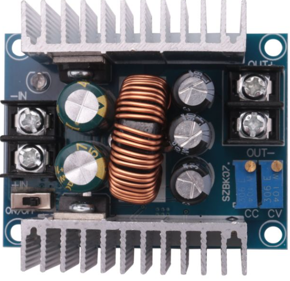
The 20A Buck 300W CC CV by Sene (Manufacturer Part ID: 300w 20A cc cv) is a high-performance DC-DC buck converter designed for efficient voltage regulation. It supports both constant current (CC) and constant voltage (CV) modes, making it suitable for a wide range of applications. With a maximum output current of 20A and a power rating of 300W, this converter is ideal for powering high-current devices, battery charging, and LED drivers.
Explore Projects Built with 20A Buck 300W cc cv
 Open Project in Cirkit Designer
 Open Project in Cirkit Designer
 Open Project in Cirkit Designer
 Open Project in Cirkit Designer
Explore Projects Built with 20A Buck 300W cc cv
Open Project in Cirkit DesignerOpen Project in Cirkit DesignerOpen Project in Cirkit DesignerOpen Project in Cirkit DesignerCommon Applications
- Battery charging (e.g., lithium-ion, lead-acid batteries)
- LED lighting systems
- Powering high-current DC motors
- Voltage regulation in renewable energy systems (e.g., solar panels)
- Laboratory power supplies
Technical Specifications
Key Technical Details
| Parameter | Value |
|---|---|
| Input Voltage Range | 8V to 60V |
| Output Voltage Range | 1.25V to 36V |
| Maximum Output Current | 20A |
| Maximum Output Power | 300W |
| Efficiency | Up to 95% |
| Operating Modes | Constant Voltage (CV), Constant Current (CC) |
| Operating Temperature | -40°C to +85°C |
| Dimensions | 60mm x 52mm x 22mm |
Pin Configuration and Descriptions
| Pin Name | Description |
|---|---|
| VIN+ | Positive input voltage terminal (connect to the DC power source) |
| VIN- | Negative input voltage terminal (connect to the DC power source ground) |
| VOUT+ | Positive output voltage terminal (connect to the load) |
| VOUT- | Negative output voltage terminal (connect to the load ground) |
| CC ADJ | Potentiometer for adjusting the constant current limit |
| CV ADJ | Potentiometer for adjusting the constant voltage output |
Usage Instructions
How to Use the Component in a Circuit
Connect the Input Voltage:
- Connect the positive terminal of your DC power source to the VIN+ pin.
- Connect the negative terminal of your DC power source to the VIN- pin.
- Ensure the input voltage is within the range of 8V to 60V.
Connect the Load:
- Connect the positive terminal of your load to the VOUT+ pin.
- Connect the negative terminal of your load to the VOUT- pin.
Adjust the Output Voltage:
- Use the CV ADJ potentiometer to set the desired output voltage.
- Turn clockwise to increase the voltage and counterclockwise to decrease it.
Set the Current Limit:
- Use the CC ADJ potentiometer to set the maximum output current.
- Turn clockwise to increase the current limit and counterclockwise to decrease it.
Power On:
- Once all connections are secure, power on the DC source.
- Verify the output voltage and current using a multimeter.
Important Considerations and Best Practices
- Heat Dissipation: The module can generate significant heat under high loads. Use an appropriate heatsink or active cooling to prevent overheating.
- Input Voltage: Ensure the input voltage is at least 2V higher than the desired output voltage for proper operation.
- Polarity: Double-check the polarity of all connections to avoid damage to the module.
- Load Testing: Before connecting sensitive devices, test the output voltage and current with a dummy load.
Example: Using with Arduino UNO
The 20A Buck 300W CC CV module can be used to power an Arduino UNO. Below is an example of how to connect and use the module:
- Set the output voltage to 5V using the CV ADJ potentiometer.
- Connect the VOUT+ pin to the Arduino's 5V pin.
- Connect the VOUT- pin to the Arduino's GND pin.
Here is a simple Arduino sketch to monitor the voltage and current using an analog sensor:
// Example code to monitor voltage and current using Arduino UNO
const int voltagePin = A0; // Analog pin for voltage measurement
const int currentPin = A1; // Analog pin for current measurement

void setup() {
  Serial.begin(9600); // Initialize serial communication
  pinMode(voltagePin, INPUT);
  pinMode(currentPin, INPUT);
}

void loop() {
  // Read the analog values
  int voltageReading = analogRead(voltagePin);
  int currentReading = analogRead(currentPin);

  // Convert readings to actual voltage and current
  float voltage = (voltageReading / 1023.0) * 5.0; // Assuming a 5V reference
  float current = (currentReading / 1023.0) * 20.0; // Assuming a 20A sensor

  // Print the values to the Serial Monitor
  Serial.print("Voltage: ");
  Serial.print(voltage);
  Serial.println(" V");

  Serial.print("Current: ");
  Serial.print(current);
  Serial.println(" A");

  delay(1000); // Wait for 1 second before the next reading
}
Troubleshooting and FAQs
Common Issues and Solutions
| Issue | Possible Cause | Solution |
|---|---|---|
| No output voltage | Incorrect wiring or loose connections | Verify all connections and polarity. |
| Output voltage not adjustable | Faulty potentiometer or incorrect setup | Check the CV ADJ potentiometer. |
| Module overheating | High load or insufficient cooling | Add a heatsink or active cooling. |
| Load not receiving enough current | Current limit set too low | Adjust the CC ADJ potentiometer. |
FAQs
Can I use this module to charge batteries?
- Yes, the constant current mode is ideal for charging batteries. Ensure you set the correct voltage and current limits for your battery type.
What happens if I exceed the input voltage range?
- Exceeding the input voltage range can damage the module. Always ensure the input voltage is within 8V to 60V.
Can I use this module with an AC power source?
- No, this module is designed for DC input only. Use a rectifier and filter circuit if you need to convert AC to DC.
How do I know if the module is in CC mode?
- The module enters CC mode when the load current reaches the set current limit. Use a multimeter to monitor the current.
This concludes the documentation for the 20A Buck 300W CC CV module by Sene.