How to Use BF9: Examples, Pinouts, and Specs
Introduction
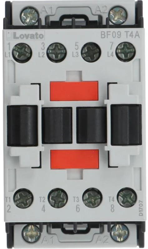
The BF9 is an NPN transistor manufactured by Lovato, designed for use in amplification and switching applications. As a versatile and reliable component, the BF9 is widely used in various electronic circuits, including audio amplifiers, signal processing, and digital switching systems. Its robust design and efficient performance make it a popular choice for both hobbyists and professionals.
Explore Projects Built with BF9


Explore Projects Built with BF9
Common Applications
- Audio signal amplification
- Digital switching circuits
- Motor control systems
- Oscillator circuits
- General-purpose electronic projects
Technical Specifications
The BF9 transistor is characterized by its ability to handle moderate power levels and its fast switching capabilities. Below are the key technical details:
| Parameter | Value |
|---|---|
| Transistor Type | NPN |
| Maximum Collector-Emitter Voltage (VCEO) | 60V |
| Maximum Collector-Base Voltage (VCBO) | 80V |
| Maximum Emitter-Base Voltage (VEBO) | 5V |
| Maximum Collector Current (IC) | 1A |
| Power Dissipation (PD) | 500mW |
| DC Current Gain (hFE) | 100 - 300 |
| Transition Frequency (fT) | 150 MHz |
| Package Type | TO-92 |
| Operating Temperature | -55°C to +150°C |
Pin Configuration
The BF9 transistor comes in a TO-92 package with three pins. The pinout is as follows:
| Pin Number | Pin Name | Description |
|---|---|---|
| 1 | Emitter | Current flows out of this pin. |
| 2 | Base | Controls the transistor's operation. |
| 3 | Collector | Current flows into this pin. |
Usage Instructions
The BF9 transistor can be used in a variety of circuits for amplification or switching purposes. Below are the steps and considerations for using the BF9:
Using the BF9 in a Circuit
- Determine the Configuration: Decide whether the transistor will be used in common-emitter, common-base, or common-collector configuration based on your application.
- Connect the Pins:
- Connect the emitter to ground or the negative terminal of the power supply.
- Connect the collector to the load (e.g., a resistor, motor, or LED) and then to the positive terminal of the power supply.
- Use a resistor to connect the base to the input signal or control voltage to limit the base current.
- Calculate Resistor Values:
- Use Ohm's Law and the transistor's current gain (hFE) to calculate the appropriate base resistor value.
- Ensure the base current (IB) is sufficient to drive the desired collector current (IC).
Example: Switching an LED with an Arduino UNO
The BF9 can be used to control an LED with an Arduino UNO. Below is an example circuit and code:
Circuit Connections
- Connect the emitter of the BF9 to ground.
- Connect the collector to one terminal of the LED. The other terminal of the LED should connect to a 220Ω resistor, which is then connected to the 5V pin of the Arduino.
- Connect the base to a 1kΩ resistor, which is then connected to a digital pin (e.g., pin 9) of the Arduino.
Arduino Code
// Define the pin connected to the BF9 transistor's base
const int transistorBasePin = 9;

void setup() {
  // Set the transistor base pin as an output
  pinMode(transistorBasePin, OUTPUT);
}

void loop() {
  // Turn the LED on by sending a HIGH signal to the transistor base
  digitalWrite(transistorBasePin, HIGH);
  delay(1000); // Keep the LED on for 1 second

  // Turn the LED off by sending a LOW signal to the transistor base
  digitalWrite(transistorBasePin, LOW);
  delay(1000); // Keep the LED off for 1 second
}
Best Practices
- Always use a base resistor to limit the base current and prevent damage to the transistor.
- Ensure the transistor operates within its maximum voltage, current, and power ratings.
- Use a heat sink if the transistor is expected to dissipate significant power.
Troubleshooting and FAQs
Common Issues
Transistor Not Switching Properly:
- Cause: Insufficient base current.
- Solution: Check the base resistor value and ensure it allows enough current to drive the transistor.
Overheating:
- Cause: Exceeding the power dissipation limit.
- Solution: Use a heat sink or reduce the load current.
No Output Signal:
- Cause: Incorrect pin connections.
- Solution: Verify the emitter, base, and collector connections.
LED Not Turning On:
- Cause: Incorrect resistor value or damaged transistor.
- Solution: Check the resistor value and replace the transistor if necessary.
FAQs
Q1: Can the BF9 be used for high-frequency applications?
A1: Yes, the BF9 has a transition frequency (fT) of 150 MHz, making it suitable for high-frequency applications.
Q2: What is the maximum load current the BF9 can handle?
A2: The BF9 can handle a maximum collector current (IC) of 1A.
Q3: Can I use the BF9 without a base resistor?
A3: No, a base resistor is essential to limit the base current and prevent damage to the transistor.
Q4: Is the BF9 suitable for driving motors?
A4: Yes, the BF9 can drive small motors, provided the current does not exceed 1A. For larger motors, consider using a transistor with a higher current rating.
By following this documentation, you can effectively use the BF9 transistor in your electronic projects.