How to Use WS7040 PCB: Examples, Pinouts, and Specs
Introduction
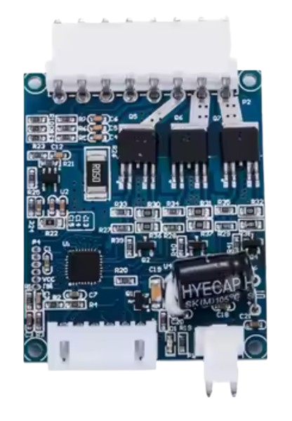
The WS7040 PCB is a printed circuit board designed for the WS7040 series, providing a robust platform for mounting and interconnecting various electronic components. This PCB is commonly used in a wide range of electronic applications, including prototyping, educational projects, and small-scale production. Its versatility and ease of use make it a popular choice among hobbyists and professionals alike.
Explore Projects Built with WS7040 PCB


Explore Projects Built with WS7040 PCB
Technical Specifications
Key Technical Details
| Parameter | Value |
|---|---|
| Dimensions | 70mm x 40mm |
| Material | FR4 |
| Layers | 2 |
| Copper Thickness | 1 oz |
| Surface Finish | HASL (Hot Air Solder Leveling) |
| Hole Diameter | 0.8mm |
| Pad Size | 1.5mm |
| Voltage Rating | Up to 50V |
| Current Rating | Up to 2A |
Pin Configuration and Descriptions
| Pin Number | Pin Name | Description |
|---|---|---|
| 1 | VCC | Power supply input (3.3V - 5V) |
| 2 | GND | Ground |
| 3 | IO1 | General-purpose I/O pin 1 |
| 4 | IO2 | General-purpose I/O pin 2 |
| 5 | IO3 | General-purpose I/O pin 3 |
| 6 | IO4 | General-purpose I/O pin 4 |
| 7 | IO5 | General-purpose I/O pin 5 |
| 8 | IO6 | General-purpose I/O pin 6 |
| 9 | IO7 | General-purpose I/O pin 7 |
| 10 | IO8 | General-purpose I/O pin 8 |
Usage Instructions
How to Use the Component in a Circuit
Power Supply:
- Connect the VCC pin to a power source (3.3V to 5V).
- Connect the GND pin to the ground of your power source.
Connecting I/O Pins:
- Use the general-purpose I/O pins (IO1 to IO8) to interface with other components such as sensors, LEDs, or actuators.
- Ensure that the voltage levels of the connected components are compatible with the WS7040 PCB.
Mounting Components:
- Solder the electronic components onto the PCB pads.
- Use appropriate soldering techniques to avoid damaging the PCB or components.
Important Considerations and Best Practices
- Avoid Overheating: When soldering, avoid excessive heat to prevent damage to the PCB and components.
- Check Connections: Double-check all connections to ensure there are no short circuits or open connections.
- Use Proper Tools: Use appropriate tools such as a soldering iron, multimeter, and wire cutters for assembly and testing.
- Follow Safety Guidelines: Always follow safety guidelines when working with electronic components and tools.
Troubleshooting and FAQs
Common Issues Users Might Face
No Power to the PCB:
- Solution: Check the power supply connections to ensure VCC and GND are properly connected.
Short Circuits:
- Solution: Inspect the PCB for solder bridges or misplaced components. Use a multimeter to check for continuity.
Component Not Responding:
- Solution: Verify that the component is correctly connected to the appropriate I/O pin and that the pin is properly configured in your code.
Solutions and Tips for Troubleshooting
- Use a Multimeter: A multimeter can help diagnose issues such as continuity, voltage levels, and short circuits.
- Check Solder Joints: Ensure all solder joints are clean and properly made. Re-solder any joints that appear cold or cracked.
- Verify Code: If using a microcontroller like Arduino, ensure your code is correctly written and uploaded.
Example Code for Arduino UNO
// Example code to blink an LED connected to IO1 of WS7040 PCB

const int ledPin = 3; // IO1 pin on WS7040 PCB

void setup() {
  pinMode(ledPin, OUTPUT); // Set the IO1 pin as an output
}

void loop() {
  digitalWrite(ledPin, HIGH); // Turn the LED on
  delay(1000);                // Wait for 1 second
  digitalWrite(ledPin, LOW);  // Turn the LED off
  delay(1000);                // Wait for 1 second
}
This example code demonstrates how to blink an LED connected to the IO1 pin of the WS7040 PCB using an Arduino UNO. Ensure that the LED is connected with the anode to IO1 and the cathode to GND.
By following this documentation, users can effectively utilize the WS7040 PCB in their electronic projects, ensuring proper usage and troubleshooting common issues.