Cirkit Designer Logo
Cirkit Designer
Your all-in-one circuit design IDE
Home / 
Component Documentation

How to Use moc3021: Examples, Pinouts, and Specs

Image of moc3021
Cirkit Designer LogoDesign with moc3021 in Cirkit Designer

Introduction

The MOC3021 is an optoisolator designed to provide electrical isolation between its input and output. It consists of an infrared light-emitting diode (LED) on the input side and a phototransistor on the output side. This configuration allows the MOC3021 to transfer signals between two electrically isolated circuits, making it ideal for controlling high-voltage circuits using low-voltage signals.

Explore Projects Built with moc3021

Use Cirkit Designer to design, explore, and prototype these projects online. Some projects support real-time simulation. Click "Open Project" to start designing instantly!
ESP32-Based Multi-Sensor Monitoring System with Bluetooth and Camera Integration
Image of cd 1: A project utilizing moc3021 in a practical application
This circuit appears to be a complex, multi-functional system involving sensor data acquisition, processing, and wireless communication. It includes an ESP32 microcontroller for general control, interfaced with a MAX30102 pulse oximeter for health monitoring, an OV7725 camera module for image capture, a potentiometer for analog input, a rotary encoder for user input, a capacitive sensor for touch detection, and an HC-05 Bluetooth module for wireless data transmission. Additionally, there is a Tower Pro SG90 servo motor which can be controlled by the ESP32, likely for some form of actuation or movement in response to the sensor inputs or remote commands received via Bluetooth.
Cirkit Designer LogoOpen Project in Cirkit Designer
Arduino Mega 2560 Based Security System with Fingerprint Authentication and SMS Alerts
Image of Door security system: A project utilizing moc3021 in a practical application
This circuit features an Arduino Mega 2560 microcontroller interfaced with a SIM800L GSM module, two fingerprint scanners, an I2C LCD display, an IR sensor, and a piezo buzzer. Power management is handled by a PowerBoost 1000 Basic Pad USB, a TP4056 charging module, and a Li-ion 18650 battery, with an option to use a Mini AC-DC 110V-230V to 5V 700mA module for direct power supply. The primary functionality appears to be a security system with GSM communication capabilities, biometric access control, and visual/audible feedback.
Cirkit Designer LogoOpen Project in Cirkit Designer
Arduino Mega 2560-Controlled Servo System with Bluetooth and Sensor Interface
Image of Završni: A project utilizing moc3021 in a practical application
This is a microcontroller-based control system featuring an Arduino Mega 2560, designed to receive inputs from a rotary potentiometer, push switches, and an IR sensor, and to drive multiple servos and an LCD display. It includes an HC-05 Bluetooth module for wireless communication, allowing for remote interfacing and control.
Cirkit Designer LogoOpen Project in Cirkit Designer
Battery-Powered Health Monitoring System with Nucleo WB55RG and OLED Display
Image of Pulsefex: A project utilizing moc3021 in a practical application
This circuit is a multi-sensor data acquisition system that uses a Nucleo WB55RG microcontroller to interface with a digital temperature sensor (TMP102), a pulse oximeter and heart-rate sensor (MAX30102), and a 0.96" OLED display via I2C. Additionally, it includes a Sim800l module for GSM communication, powered by a 3.7V LiPo battery.
Cirkit Designer LogoOpen Project in Cirkit Designer

Explore Projects Built with moc3021

Use Cirkit Designer to design, explore, and prototype these projects online. Some projects support real-time simulation. Click "Open Project" to start designing instantly!
Image of cd 1: A project utilizing moc3021 in a practical application
ESP32-Based Multi-Sensor Monitoring System with Bluetooth and Camera Integration
This circuit appears to be a complex, multi-functional system involving sensor data acquisition, processing, and wireless communication. It includes an ESP32 microcontroller for general control, interfaced with a MAX30102 pulse oximeter for health monitoring, an OV7725 camera module for image capture, a potentiometer for analog input, a rotary encoder for user input, a capacitive sensor for touch detection, and an HC-05 Bluetooth module for wireless data transmission. Additionally, there is a Tower Pro SG90 servo motor which can be controlled by the ESP32, likely for some form of actuation or movement in response to the sensor inputs or remote commands received via Bluetooth.
Cirkit Designer LogoOpen Project in Cirkit Designer
Image of Door security system: A project utilizing moc3021 in a practical application
Arduino Mega 2560 Based Security System with Fingerprint Authentication and SMS Alerts
This circuit features an Arduino Mega 2560 microcontroller interfaced with a SIM800L GSM module, two fingerprint scanners, an I2C LCD display, an IR sensor, and a piezo buzzer. Power management is handled by a PowerBoost 1000 Basic Pad USB, a TP4056 charging module, and a Li-ion 18650 battery, with an option to use a Mini AC-DC 110V-230V to 5V 700mA module for direct power supply. The primary functionality appears to be a security system with GSM communication capabilities, biometric access control, and visual/audible feedback.
Cirkit Designer LogoOpen Project in Cirkit Designer
Image of Završni: A project utilizing moc3021 in a practical application
Arduino Mega 2560-Controlled Servo System with Bluetooth and Sensor Interface
This is a microcontroller-based control system featuring an Arduino Mega 2560, designed to receive inputs from a rotary potentiometer, push switches, and an IR sensor, and to drive multiple servos and an LCD display. It includes an HC-05 Bluetooth module for wireless communication, allowing for remote interfacing and control.
Cirkit Designer LogoOpen Project in Cirkit Designer
Image of Pulsefex: A project utilizing moc3021 in a practical application
Battery-Powered Health Monitoring System with Nucleo WB55RG and OLED Display
This circuit is a multi-sensor data acquisition system that uses a Nucleo WB55RG microcontroller to interface with a digital temperature sensor (TMP102), a pulse oximeter and heart-rate sensor (MAX30102), and a 0.96" OLED display via I2C. Additionally, it includes a Sim800l module for GSM communication, powered by a 3.7V LiPo battery.
Cirkit Designer LogoOpen Project in Cirkit Designer

Common Applications and Use Cases

  • AC and DC motor control
  • Signal isolation in microcontroller-based systems
  • Triac triggering for AC loads
  • Industrial automation and control systems
  • Protection of sensitive low-voltage circuits from high-voltage transients

Technical Specifications

The MOC3021 is a robust and versatile component. Below are its key technical details:

Parameter Value
Input LED Forward Voltage 1.2V (typical), 1.5V (maximum)
Input LED Forward Current 10mA (typical), 60mA (maximum)
Output Voltage (VCEO) 400V (maximum)
Isolation Voltage 5000Vrms
Trigger LED Current (IFT) 15mA (maximum)
Output Current (IO) 100mA (maximum)
Operating Temperature Range -40°C to +100°C
Package Type 6-pin DIP

Pin Configuration and Descriptions

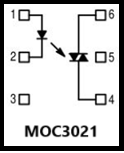
The MOC3021 is housed in a 6-pin DIP package. The pinout is as follows:

Pin Number Name Description
1 Anode Positive terminal of the input LED. Connect to the control signal.
2 Cathode Negative terminal of the input LED. Connect to ground or a current-limiting resistor.
3 NC (No Connect) Not connected internally. Leave unconnected.
4 Emitter Emitter of the phototransistor. Connect to the load or ground.
5 Collector Collector of the phototransistor. Connect to the high-voltage side of the circuit.
6 NC (No Connect) Not connected internally. Leave unconnected.

Usage Instructions

The MOC3021 is commonly used to trigger a triac for AC load control or to isolate signals between two circuits. Below are the steps and considerations for using the MOC3021 in a circuit:

Basic Circuit Design

  1. Input Side (LED):

    • Connect the anode (Pin 1) to the control signal through a current-limiting resistor.
    • Connect the cathode (Pin 2) to ground.
    • Calculate the resistor value using Ohm's Law:
      [ R = \frac{V_{in} - V_f}{I_f} ]
      Where (V_{in}) is the input voltage, (V_f) is the forward voltage of the LED (1.2V typical), and (I_f) is the desired forward current (10mA typical).
  2. Output Side (Phototransistor):

    • Connect the collector (Pin 5) to the high-voltage side of the circuit.
    • Connect the emitter (Pin 4) to the load or ground, depending on the application.

Example: Triac Triggering Circuit

The MOC3021 is often used to trigger a triac for controlling AC loads. Below is an example circuit:

  • Input: Microcontroller GPIO pin
  • Output: Triac controlling an AC load

Arduino Example Code

The following code demonstrates how to use the MOC3021 with an Arduino UNO to control an AC load:

// Define the pin connected to the MOC3021 input
const int moc3021Pin = 9;

void setup() {
  pinMode(moc3021Pin, OUTPUT); // Set the pin as an output
}

void loop() {
  digitalWrite(moc3021Pin, HIGH); // Turn on the AC load
  delay(1000);                    // Keep it on for 1 second
  digitalWrite(moc3021Pin, LOW);  // Turn off the AC load
  delay(1000);                    // Keep it off for 1 second
}

Important Considerations

  • Always use a current-limiting resistor on the input side to prevent damage to the LED.
  • Ensure proper heat dissipation if the MOC3021 is used near its maximum current ratings.
  • For AC load control, use a snubber circuit across the triac to suppress voltage spikes.

Troubleshooting and FAQs

Common Issues

  1. No Output Signal:

    • Check if the input LED is receiving sufficient current. Verify the resistor value.
    • Ensure the input control signal is within the required voltage range.
  2. Erratic Behavior in AC Load Control:

    • Verify the triac and snubber circuit connections.
    • Check for noise or interference in the control signal.
  3. Component Overheating:

    • Ensure the current on both the input and output sides does not exceed the maximum ratings.
    • Use proper heat sinks or cooling mechanisms if necessary.

FAQs

Q: Can the MOC3021 be used for DC load control?
A: Yes, the MOC3021 can be used for DC load control, but it is more commonly used for AC load control due to its ability to trigger triacs.

Q: What is the purpose of the isolation voltage rating?
A: The isolation voltage rating (5000Vrms) indicates the maximum voltage the MOC3021 can withstand between its input and output without electrical breakdown, ensuring safe isolation.

Q: Can I use the MOC3021 directly with a microcontroller?
A: Yes, the MOC3021 can be directly interfaced with a microcontroller, provided a suitable current-limiting resistor is used on the input side.

By following the guidelines and best practices outlined in this documentation, you can effectively use the MOC3021 in your electronic projects.