How to Use 15A single DC motor driver: Examples, Pinouts, and Specs
Introduction
The AQMH3615NS is a high-performance single DC motor driver designed to control the speed and direction of a DC motor. With a current handling capacity of up to 15A, this motor driver is ideal for applications requiring robust and reliable motor control. It is commonly used in robotics, automation systems, electric vehicles, and other motor-driven projects.
This motor driver allows for precise control of motor speed and direction through Pulse Width Modulation (PWM) and directional input signals. Its compact design and high current capacity make it suitable for both hobbyist and industrial applications.
Explore Projects Built with 15A single DC motor driver
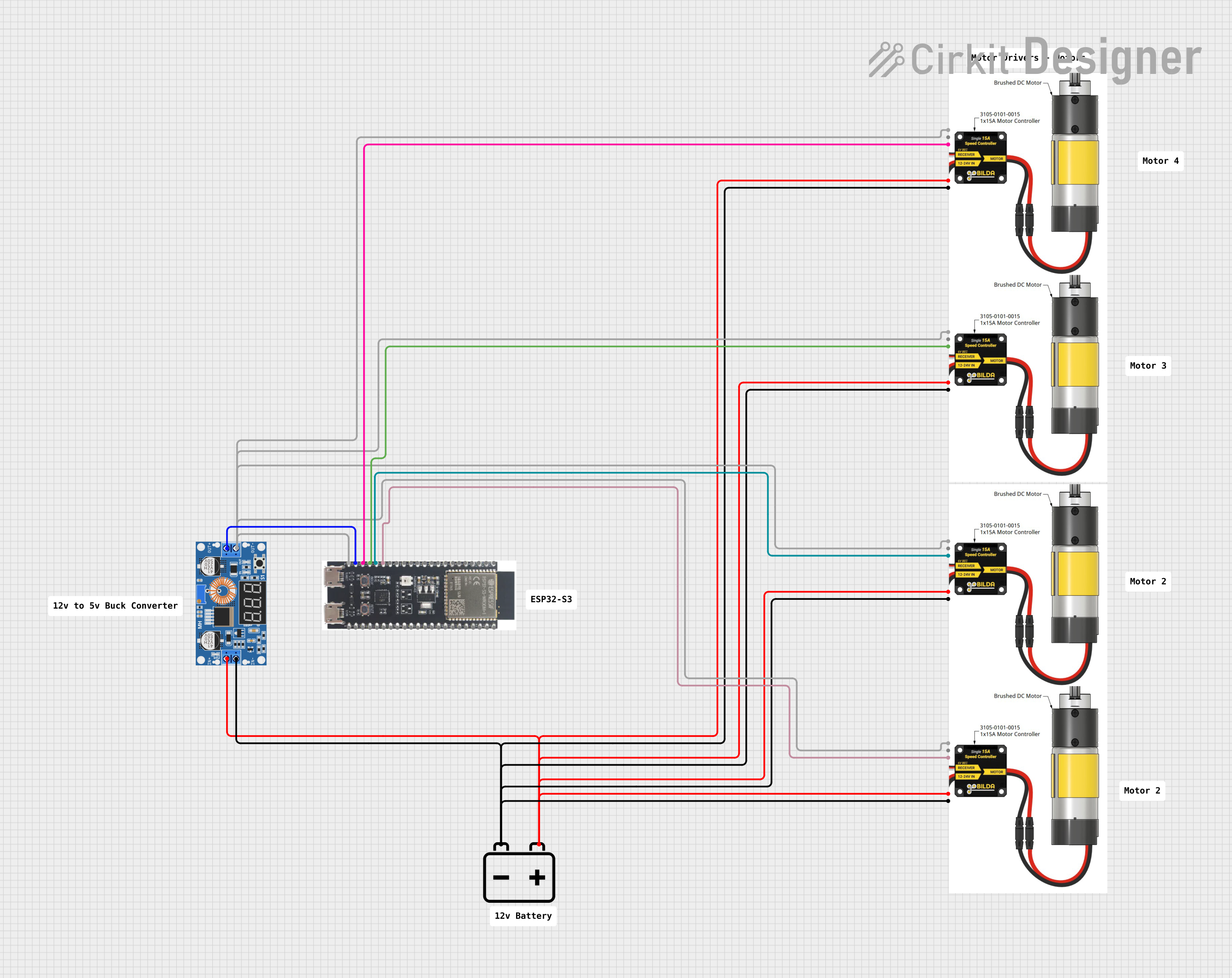
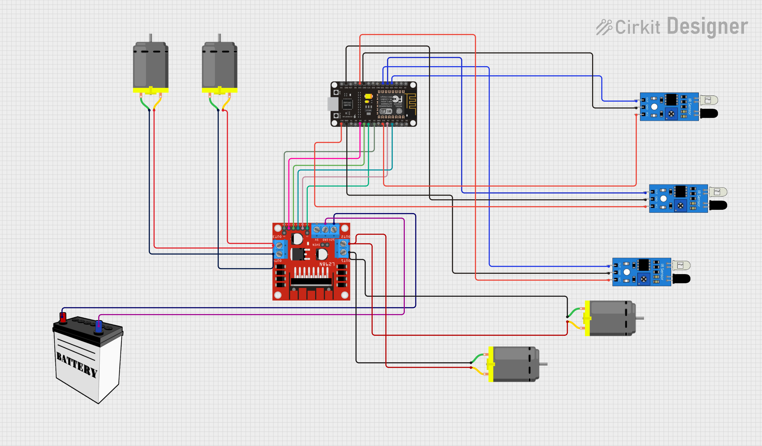
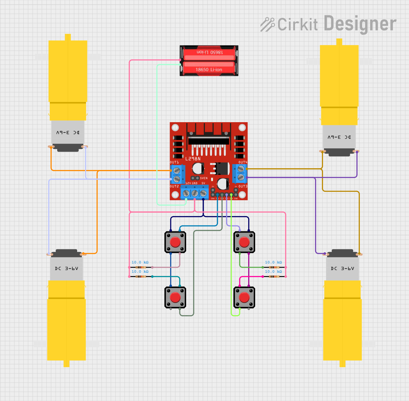

Explore Projects Built with 15A single DC motor driver
Technical Specifications
Below are the key technical details of the AQMH3615NS motor driver:
| Parameter | Value |
|---|---|
| Operating Voltage Range | 6V to 30V |
| Maximum Continuous Current | 15A |
| Peak Current | 30A (for short durations) |
| Control Signal Voltage | 3.3V or 5V logic compatible |
| PWM Frequency Range | Up to 20 kHz |
| Operating Temperature | -20°C to 85°C |
| Dimensions | 50mm x 40mm x 15mm |
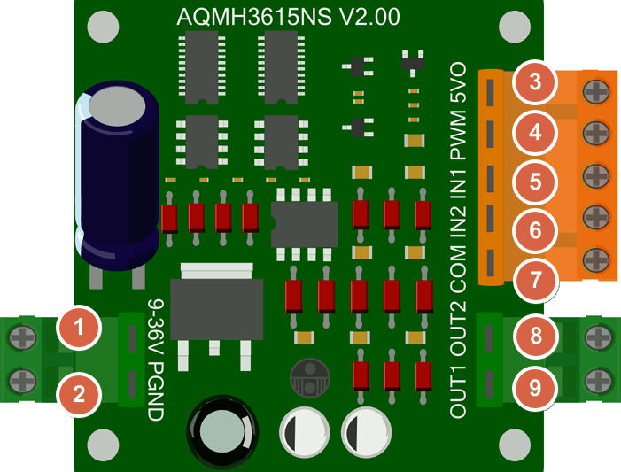
Pin Configuration and Descriptions
The AQMH3615NS motor driver has the following pin configuration:
| Pin Name | Pin Type | Description |
|---|---|---|
| VIN | Power Input | Connect to the positive terminal of the power supply (6V to 30V). |
| GND | Power Ground | Connect to the ground terminal of the power supply and motor. |
| OUT1 | Motor Output | Connect to one terminal of the DC motor. |
| OUT2 | Motor Output | Connect to the other terminal of the DC motor. |
| EN | Enable Input | Active HIGH. Enables the motor driver when set to HIGH. |
| PWM | PWM Input | Provides speed control for the motor. Accepts PWM signals (3.3V or 5V logic). |
| DIR | Direction Input | Controls the direction of the motor. HIGH for one direction, LOW for the other. |
Usage Instructions
How to Use the Component in a Circuit
- Power Supply: Connect the VIN pin to a DC power supply (6V to 30V) capable of providing sufficient current for your motor. Connect the GND pin to the ground of the power supply.
- Motor Connection: Connect the two terminals of your DC motor to the OUT1 and OUT2 pins.
- Control Signals:
- Connect the EN pin to a digital output pin of your microcontroller. Set it HIGH to enable the motor driver.
- Connect the PWM pin to a PWM-capable output pin of your microcontroller to control motor speed.
- Connect the DIR pin to a digital output pin of your microcontroller to control motor direction.
- Logic Voltage Compatibility: Ensure that the control signals (EN, PWM, DIR) are compatible with 3.3V or 5V logic levels.
Important Considerations and Best Practices
- Heat Dissipation: The AQMH3615NS can handle high currents, but prolonged operation at maximum current may cause overheating. Use a heat sink or active cooling if necessary.
- Power Supply: Ensure your power supply can provide sufficient current for both the motor and the driver.
- Decoupling Capacitors: Place a decoupling capacitor (e.g., 100µF) across the VIN and GND pins to reduce voltage spikes.
- Reverse Polarity Protection: The driver does not include reverse polarity protection. Double-check your connections before powering the circuit.
Example Code for Arduino UNO
Below is an example of how to control the AQMH3615NS motor driver using an Arduino UNO:
// Pin definitions
const int EN_PIN = 9;    // Enable pin connected to Arduino digital pin 9
const int PWM_PIN = 10;  // PWM pin connected to Arduino digital pin 10
const int DIR_PIN = 8;   // Direction pin connected to Arduino digital pin 8

void setup() {
  // Set pin modes
  pinMode(EN_PIN, OUTPUT);
  pinMode(PWM_PIN, OUTPUT);
  pinMode(DIR_PIN, OUTPUT);

  // Enable the motor driver
  digitalWrite(EN_PIN, HIGH);
}

void loop() {
  // Set motor direction to forward
  digitalWrite(DIR_PIN, HIGH);

  // Gradually increase motor speed
  for (int speed = 0; speed <= 255; speed++) {
    analogWrite(PWM_PIN, speed); // Set PWM duty cycle (0-255)
    delay(20);                   // Wait 20ms
  }

  // Gradually decrease motor speed
  for (int speed = 255; speed >= 0; speed--) {
    analogWrite(PWM_PIN, speed); // Set PWM duty cycle (0-255)
    delay(20);                   // Wait 20ms
  }

  // Set motor direction to reverse
  digitalWrite(DIR_PIN, LOW);

  // Repeat the speed ramp-up and ramp-down
  for (int speed = 0; speed <= 255; speed++) {
    analogWrite(PWM_PIN, speed);
    delay(20);
  }
  for (int speed = 255; speed >= 0; speed--) {
    analogWrite(PWM_PIN, speed);
    delay(20);
  }
}
Troubleshooting and FAQs
Common Issues and Solutions
Motor Not Running:
- Ensure the EN pin is set HIGH to enable the motor driver.
- Verify that the power supply voltage is within the specified range (6V to 30V).
- Check all connections, especially the motor and power supply connections.
Motor Running in the Wrong Direction:
- Check the DIR pin signal. Set it HIGH for one direction and LOW for the other.
- Verify the motor connections to OUT1 and OUT2.
Motor Speed Not Changing:
- Ensure the PWM signal is being generated correctly by the microcontroller.
- Verify that the PWM frequency is within the supported range (up to 20 kHz).
Overheating:
- Check if the motor is drawing more current than the driver’s maximum continuous current (15A).
- Use a heat sink or active cooling to dissipate heat.
FAQs
Q1: Can I use this motor driver with a 3.3V microcontroller?
A1: Yes, the AQMH3615NS is compatible with both 3.3V and 5V logic levels.
Q2: What happens if I exceed the maximum current rating?
A2: Exceeding the 15A continuous current rating may cause the driver to overheat or fail. Use a current-limiting circuit or fuse for protection.
Q3: Can I control the motor driver without a microcontroller?
A3: Yes, you can use external switches or a signal generator to control the EN, PWM, and DIR pins.
Q4: Is reverse polarity protection included?
A4: No, the AQMH3615NS does not include reverse polarity protection. Double-check your connections before powering the circuit.