How to Use 433 MHz RF Transmitter: Examples, Pinouts, and Specs
Introduction
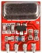
The 433 MHz RF Transmitter is a compact and cost-effective device designed to transmit radio frequency signals at 433 MHz. It is widely used in wireless communication systems for short-range data transmission. This component is ideal for applications such as remote control systems, wireless sensor networks, home automation, and IoT (Internet of Things) devices. Its simplicity and low power consumption make it a popular choice for hobbyists and professionals alike.
Explore Projects Built with 433 MHz RF Transmitter


Explore Projects Built with 433 MHz RF Transmitter
Technical Specifications
- Frequency: 433 MHz
- Operating Voltage: 3V to 12V DC (typical: 5V)
- Operating Current: 9 mA (at 5V)
- Transmission Range: Up to 100 meters (line of sight, depending on antenna and environment)
- Modulation Type: Amplitude Shift Keying (ASK)
- Data Rate: Up to 10 kbps
- Antenna: External wire antenna (recommended length: ~17 cm for 433 MHz)
Pin Configuration and Descriptions
The 433 MHz RF Transmitter module typically has 4 pins. Below is the pinout:
| Pin | Name | Description |
|---|---|---|
| 1 | VCC | Power supply pin. Connect to 3V-12V DC (5V is commonly used). |
| 2 | DATA | Data input pin. Connect to the microcontroller or data source. |
| 3 | GND | Ground pin. Connect to the ground of the power supply and circuit. |
| 4 | ANT | Antenna pin. Connect a wire antenna (~17 cm) for optimal signal transmission. |
Usage Instructions
How to Use the 433 MHz RF Transmitter in a Circuit
- Power the Module: Connect the VCC pin to a 5V power source and the GND pin to the ground.
- Connect the Data Pin: Attach the DATA pin to the microcontroller's digital output pin or any data source.
- Add an Antenna: Solder a 17 cm wire to the ANT pin to act as an antenna. This improves the transmission range.
- Transmit Data: Send digital signals (e.g., HIGH/LOW) to the DATA pin to transmit information wirelessly.
Important Considerations and Best Practices
- Antenna Placement: Ensure the antenna is straight and positioned away from other components to avoid interference.
- Power Supply: Use a stable power source to prevent noise or fluctuations that could affect transmission quality.
- Data Encoding: Use a suitable encoding protocol (e.g., Manchester encoding) to ensure reliable data transmission.
- Pairing with Receiver: Use a compatible 433 MHz RF Receiver module to decode the transmitted signals.
- Environment: The transmission range may vary depending on obstacles, interference, and environmental conditions.
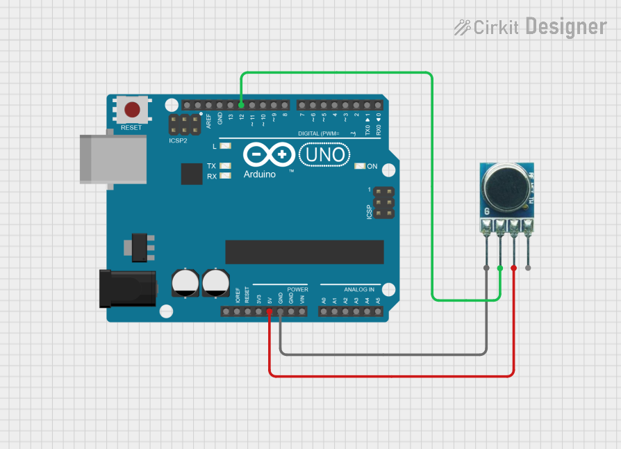
Example: Using the 433 MHz RF Transmitter with Arduino UNO
Below is an example of how to use the 433 MHz RF Transmitter with an Arduino UNO to send a simple signal:
// Include the RadioHead library for RF communication
#include <RH_ASK.h>
#include <SPI.h> // Required for RadioHead library compatibility

// Initialize the RF transmitter object
RH_ASK rf_driver;

void setup() {
  // Initialize the RF driver
  if (!rf_driver.init()) {
    // Print an error message if initialization fails
    Serial.println("RF Transmitter initialization failed!");
    while (1); // Halt the program
  }
  Serial.begin(9600); // Start serial communication for debugging
}

void loop() {
  const char *message = "Hello, World!"; // Message to transmit
  rf_driver.send((uint8_t *)message, strlen(message)); // Send the message
  rf_driver.waitPacketSent(); // Wait for the transmission to complete
  delay(1000); // Wait 1 second before sending the next message
}
Note: The above code uses the RadioHead library, which must be installed in the Arduino IDE. You can install it via the Library Manager.
Troubleshooting and FAQs
Common Issues and Solutions
No Signal Received:
- Ensure the transmitter and receiver are operating at the same frequency (433 MHz).
- Check the antenna connection and ensure it is the correct length (~17 cm).
- Verify that the power supply voltage is within the specified range (3V-12V).
Short Transmission Range:
- Ensure the antenna is properly positioned and not obstructed by metal objects.
- Increase the power supply voltage (up to 12V) for a stronger signal, if supported by your circuit.
- Minimize interference from other RF devices operating at 433 MHz.
Data Corruption:
- Use a reliable encoding protocol (e.g., Manchester encoding) to reduce errors.
- Ensure the data rate does not exceed the module's maximum supported rate (10 kbps).
FAQs
Q1: Can I use the 433 MHz RF Transmitter without an antenna?
A1: While the module may work without an antenna, the transmission range will be significantly reduced. It is highly recommended to use a 17 cm wire antenna for optimal performance.
Q2: What is the maximum range of the 433 MHz RF Transmitter?
A2: The maximum range is up to 100 meters in line-of-sight conditions. Obstacles, interference, and improper antenna placement can reduce the range.
Q3: Can I use multiple transmitters in the same area?
A3: Yes, but you must implement a protocol to avoid signal collisions, as multiple transmitters operating simultaneously can interfere with each other.
Q4: Is the 433 MHz RF Transmitter compatible with other frequencies?
A4: No, this module is specifically designed to operate at 433 MHz. For other frequencies, you will need a different transmitter module.
Q5: Can I use this module for audio or video transmission?
A5: No, the 433 MHz RF Transmitter is designed for low-bandwidth digital data transmission and is not suitable for audio or video signals.